


13--8--625
Page 32
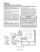
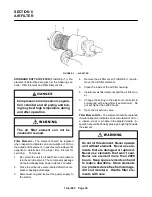
FIGURE 5--5 -- OIL FILTER
Compressor, air/oil reservoir, separa-
tion chamber and all piping and tub-
ing may be at high temperature during
and after operation.
1.
Stop unit and be sure no air pressure is in the oil
reservoir.
2.
Disconnect, tag and lock out the power supply to
the starter.
3.
Remove the spin--on element.
4.
Clean the gasket face of the filter body.
5.
Coat the new element gasket with clean lubricant
used in the unit.
6.
Screw new element on filter body and tighten by
hand. DO NOT OVERTIGHTEN ELEMENT.
7.
Run the unit and check for leaks.
COMPRESSOR OIL COOLER -- The cooler fan is
mounted on the compressor motor shaft; air is ex-
hausted through the oil cooler and away from the unit.
Do not obstruct air flow to and from the oil cooler. Allow
a minimum of two (2) feet (.6M) clearance around the
cooler. Keep both faces of the cooler core clean for effi-
cient cooling of compressor oil.
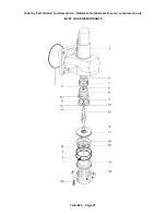
THERMAL CONTROL (THERMOSTATIC MIXING)
VALVE (FIGURE 5--1, page 27) is installed in the sys-
tem. This valve is used to control the temperature of
the oil. On start--up with unit cold, the element is open
to bypass, allowing oil to pass directly from the reser-
voir to compressor during warm--up. As oil warms, the
element gradually closes to the bypass allowing more
of the oil from the cooler to mix with oil from the bypass.
After the unit is warmed up, the mixing valve maintains
oil injection temperature into the compressor at a mini-
mum of 130
_
F (54
_
C). This system provides proper
compressor warm--up and prevents moisture contami-
nation of the oil.
To check the element, heat in oil -- it should be fully ex-
tended at 130
_
F (54
_
C). If the unit shuts down due to
high air discharge temperature, the cause may be that
the element is stuck open to the bypass. When flushing
Содержание EFD-25 HP
Страница 13: ...13 8 616 Page 4 DECALS 206EAQ077 212EAQ077 218EAQ077 211EAQ077 207EAQ077...
Страница 14: ...13 8 616 Page 5 DECALS 216EAQ077 217EAQ077 222EAQ077 221EAQ077 208EAQ077...
Страница 30: ...13 8 625 Page 21 FIGURE 4 4 COMPRESSOR RUNNING FULLY LOADED...
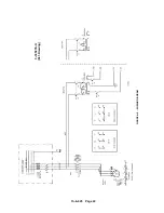
Страница 32: ...13 8 625 Page 23 FIGURE 4 5 WIRING DIAGRAM 3 305865 Ref Drawing...
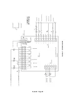
Страница 33: ...13 8 625 Page 24 FIGURE 4 6 WIRING DIAGRAM 3 305979 A Ref Drawing...
Страница 34: ...13 8 625 Page 25 FIGURE 4 7 WIRING DIAGRAM 3 305979 A Ref Drawing...
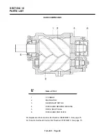
Страница 54: ...13 8 625 Page 45 AIREND GROUP...
Страница 60: ...13 8 625 Page 51 AIREND AND INLET FILTER ASSEMBLY...
Страница 62: ...13 8 625 Page 53 DRIVE GROUPS For list of Common Parts see page 54 For Drive Groups see pages 55 through 62...
Страница 72: ...13 8 625 Page 63 COOLING GROUP...
Страница 74: ...13 8 625 Page 65 CONTROL SYSTEM ASSEMBLY AND MOUNTING...
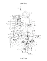
Страница 78: ...13 8 625 Page 69 CONTROL BOX 3 305979 A Ref Drawing...
Страница 80: ...13 8 625 Page 71 ENCLOSURE GROUP...


