13--8--625
Page 22
Ref.
No.
Component
1
PRESSURE TRANSDUCER
2
SOLENOID VALVE -- 3 WAY,
INLET VALVE CONTROL
3
INLET VALVE
4
AIR FILTER HOUSING
5
AIR FILTER COVER
6
AIR FILTER ELEMENT
7
AIR FILTER CLAMP
8
BLOW DOWN VALVE
9
NUT--WING
10
DIFFERENTIAL PRESSURE SWITCH
11
TUBE ELBOW
12
PIPE BUSHING
13
ELBOW
14
NIPPLE
15
DOUBLE NIPPLE
Ref.
No.
Component
16
ELBOW
17
TUBE TEE
18
TUBE
19
SCREW--SOCKET
20
TUBE
21
CLAMP
22
THERMISTOR
23
PIPE BUSHING
24
TUBE TEE
25
VALVE, BALL
26
ELBOW
27
REDUCING DOUBLE NIPPLE
29
TUBE TEE, OFFSET
30
CHECK VALVE
(For 6mm Plastic Tube)
31
PIPE BUSHING
REFERENCE NUMBER DISCRIPTION FOR FIGURE 4--4
Pressure Transducer (FIGURE 4--4, page 21) -- This
transducer is connected after the minimum pressure/
check valve. It converts the pressure in the plant air
system into an electrical signal for use by the controller.
Indication on the control panel
Cause
Pressure light flashing
Overpressure alarm causing compressor to shutdown
or pressure sensor fault
Temperature light flashing
Temperature alarm
Temperature light flashing fast
Temperature alarm, causing shutdown
Service light flashing
Oil change service alarm
Air filter light flashing
Air filter replacement required
Air filter light flashing fast
Air filter indicator switch triggered
Air/oil separator light flashing
Air/oil separator replacement required
Oil filter light flashing
Oil filter replacement required
Motor light flashing fast
Motor overloaded
All lights flashing fast
Emergency stop button depressed
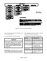
ALARMS
Содержание EFD-25 HP
Страница 13: ...13 8 616 Page 4 DECALS 206EAQ077 212EAQ077 218EAQ077 211EAQ077 207EAQ077...
Страница 14: ...13 8 616 Page 5 DECALS 216EAQ077 217EAQ077 222EAQ077 221EAQ077 208EAQ077...
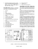
Страница 30: ...13 8 625 Page 21 FIGURE 4 4 COMPRESSOR RUNNING FULLY LOADED...
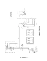
Страница 32: ...13 8 625 Page 23 FIGURE 4 5 WIRING DIAGRAM 3 305865 Ref Drawing...
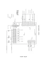
Страница 33: ...13 8 625 Page 24 FIGURE 4 6 WIRING DIAGRAM 3 305979 A Ref Drawing...
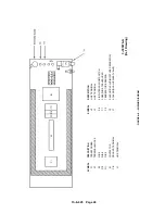
Страница 34: ...13 8 625 Page 25 FIGURE 4 7 WIRING DIAGRAM 3 305979 A Ref Drawing...
Страница 54: ...13 8 625 Page 45 AIREND GROUP...
Страница 60: ...13 8 625 Page 51 AIREND AND INLET FILTER ASSEMBLY...
Страница 62: ...13 8 625 Page 53 DRIVE GROUPS For list of Common Parts see page 54 For Drive Groups see pages 55 through 62...
Страница 72: ...13 8 625 Page 63 COOLING GROUP...
Страница 74: ...13 8 625 Page 65 CONTROL SYSTEM ASSEMBLY AND MOUNTING...
Страница 78: ...13 8 625 Page 69 CONTROL BOX 3 305979 A Ref Drawing...
Страница 80: ...13 8 625 Page 71 ENCLOSURE GROUP...

