


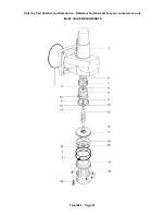
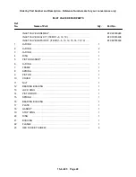


13--8--625
Page 34
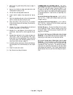
3.
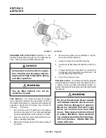
Disconnect, tag and lockout the power supply to
the starter.
4.
Remove the minimum pressure/check valve (air/
oil separator housing) cover.
5.
Lift out the air/oil separator elements.
6.
Inspect and/or replace the separator as neces-
sary.
7.
Clean the sealing surfaces on the air/oil separator
and the minimum pressure/check valve.
8.
Clean the orifice in the oil return line, the strainer
in the oil return line and if necessary the air/oil sep-
arator housing.
9.
Grease the o--ring on the separator element and
install the separator into the housing.
10. Replace the o--ring between the minimum pres-
sure/check valve and the air/oil separator hous-
ing.
11. Replace the sealing kit in the minimum pressure/
check valve. After the assembling of the valve,
leave about .08 inch gap between the nut and the
cover of the valve. See “Changing Minimum Pres-
sure/Check Valve Seals,” page 20.
12. Install the minimum pressure/check valve assem-
bly and tighten the bolts alternately for even tight-
ness.
13. Open the air service valve.
14. Run the unit and check for leaks.
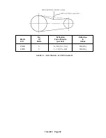
COMPRESSOR OIL SYSTEM CHECK -- The follow-
ing readings are based on ambient temperature of
80
_
F (27
_
C) with the system in good condition. The
compressor should be at operating temperature at the
time of the checks. One--half hour of loaded operation
is usually sufficient to reach level--out operating tem-
peratures.
Air and Oil Discharge Temperature -- 140
_
to 170
_
F
(60
_
to 77
_
C) -- Check with a thermometer at the dis-
charge housing.
Compressor Oil Inlet Temperature -- 130
_
to 145
_
F
(54
_
to 63
_
C) -- Install a tee at the oil filter outlet and
check with a thermometer.
Oil Inlet Pressure -- Check at the fitting in the line near
the compressor oil inlet. With air receiver pressure at
100 psi (6.9 Bar), oil inlet pressure should be 80 to 90
psig (5.5 to 6.2 Bar).
Oil Cooler Oil Pressure Differential (Air--Cooled
Radiator) -- Check differential across the oil system by
measuring oil inlet pressure as described above.
Oil Cooler Temperature Differential (Air--Cooled
Radiator) -- The oil temperature differential depends
on the temperature of the air at the oil cooler fan and
cleanliness of the core faces. As ambient tempera-
tures and core restrictions increase, the oil cooler outlet
temperature will increase. The oil inlet temperature is
approximately the same as the air discharge tempera-
ture.
Содержание EFD-25 HP
Страница 13: ...13 8 616 Page 4 DECALS 206EAQ077 212EAQ077 218EAQ077 211EAQ077 207EAQ077...
Страница 14: ...13 8 616 Page 5 DECALS 216EAQ077 217EAQ077 222EAQ077 221EAQ077 208EAQ077...
Страница 30: ...13 8 625 Page 21 FIGURE 4 4 COMPRESSOR RUNNING FULLY LOADED...
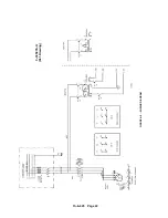
Страница 32: ...13 8 625 Page 23 FIGURE 4 5 WIRING DIAGRAM 3 305865 Ref Drawing...
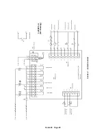
Страница 33: ...13 8 625 Page 24 FIGURE 4 6 WIRING DIAGRAM 3 305979 A Ref Drawing...
Страница 34: ...13 8 625 Page 25 FIGURE 4 7 WIRING DIAGRAM 3 305979 A Ref Drawing...
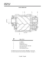
Страница 54: ...13 8 625 Page 45 AIREND GROUP...
Страница 60: ...13 8 625 Page 51 AIREND AND INLET FILTER ASSEMBLY...
Страница 62: ...13 8 625 Page 53 DRIVE GROUPS For list of Common Parts see page 54 For Drive Groups see pages 55 through 62...
Страница 72: ...13 8 625 Page 63 COOLING GROUP...
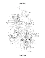
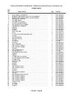
Страница 74: ...13 8 625 Page 65 CONTROL SYSTEM ASSEMBLY AND MOUNTING...
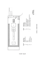
Страница 78: ...13 8 625 Page 69 CONTROL BOX 3 305979 A Ref Drawing...
Страница 80: ...13 8 625 Page 71 ENCLOSURE GROUP...


