


13--8--625
Page 19
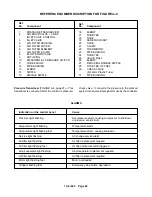
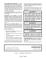
Parameter
Setting range
Factory setting
Unload pressure
45 psig to compressor maximum
Maximum pressure rating for the
pressure (see nameplate)
package as built at the factory*
Discharge pressure
45 psig to compressor maximum
differential pressure = 10 psi
pressure (see nameplate)
Automatic timer
1--20 minutes
3 or 5 minutes
Automatic start delay
0 or 10--240 seconds
0
Condensate removal, open time
1--20 seconds
2 seconds
Condensate removal, close time
10 -- 120 seconds
60 seconds
Air filter replacement interval
0--4000 hours
2000 hours
Oil change interval
0--4000 hours
4000 hours
Air/oil separator replacement
0--8000 hours
6000 hours
interval
Oil filter replacement interval
0--4000 hours
1000 hours
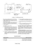
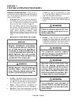
COMPRESSOR SETTINGS CHANGEABLE BY THE USER:
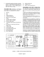
CONTROL DEVICES
CONTROLLER -- See “Airpilot Electronic Controller,”
page 13, for description.
Relief Valve -- (A) pressure relief valve(s) is (are)
installed in the final discharge line and set to approxi-
mately 120--125% of the unit’s full load operating pres-
sure for protection against over pressure. Periodic
checks should be made to ensure its (their) operation.
The relief valve should be tested for proper operation
at least once every year. To test the relief valve, raise
the system operating pressure to 75% of the relief valve
set pressure and manually open the valve with the hand
lever. Hold the valve open for a few seconds and allow
it to snap shut.
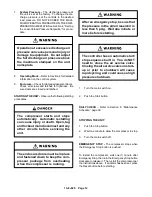
When the relief valve opens, a stream
of high velocity air is released, result-
ing in a high noise level and possible
discharge of accumulated dirt or oth-
er debris. Always wear eye and ear
protection and stand clear of the dis-
charge port when testing the relief
valve to prevent injury.
Never paint, lubricate or alter a relief
valve. Do not plug vent or restrict dis-
charge.
Operation of unit with improper relief
valve setting can result in severe per-
sonal injury or machine damage.
Insure properly set valves are in-
stalled and maintained.
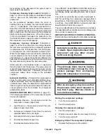
Blowdown Valve (FIGURE 4--1, page 13) -- This valve
is normally used for control functions, but also serves
to relieve air/oil reservoir pressure following a shut-
down. The blowdown valve is a pneumatic operated
valve which is piped into the air/oil reservoir, ahead of
the minimum pressure check valve. When the valve is
open, the system blows down. When the valve closes,
the system pressurizes.
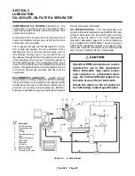
Oil Level Gauge -- This gauge is located on the oil res-
ervoir and indicates the oil level. See Section 5, page
31, for information on how to correctly read the gauge.
Minimum
Discharge
Pressure/Check
Valve
(FIGURE 5--1, page 27) -- An internal spring--loaded
Содержание EFD-25 HP
Страница 13: ...13 8 616 Page 4 DECALS 206EAQ077 212EAQ077 218EAQ077 211EAQ077 207EAQ077...
Страница 14: ...13 8 616 Page 5 DECALS 216EAQ077 217EAQ077 222EAQ077 221EAQ077 208EAQ077...
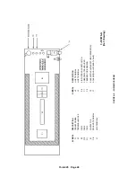
Страница 30: ...13 8 625 Page 21 FIGURE 4 4 COMPRESSOR RUNNING FULLY LOADED...
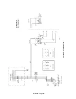
Страница 32: ...13 8 625 Page 23 FIGURE 4 5 WIRING DIAGRAM 3 305865 Ref Drawing...
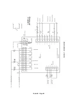
Страница 33: ...13 8 625 Page 24 FIGURE 4 6 WIRING DIAGRAM 3 305979 A Ref Drawing...
Страница 34: ...13 8 625 Page 25 FIGURE 4 7 WIRING DIAGRAM 3 305979 A Ref Drawing...
Страница 54: ...13 8 625 Page 45 AIREND GROUP...
Страница 60: ...13 8 625 Page 51 AIREND AND INLET FILTER ASSEMBLY...
Страница 62: ...13 8 625 Page 53 DRIVE GROUPS For list of Common Parts see page 54 For Drive Groups see pages 55 through 62...
Страница 72: ...13 8 625 Page 63 COOLING GROUP...
Страница 74: ...13 8 625 Page 65 CONTROL SYSTEM ASSEMBLY AND MOUNTING...
Страница 78: ...13 8 625 Page 69 CONTROL BOX 3 305979 A Ref Drawing...
Страница 80: ...13 8 625 Page 71 ENCLOSURE GROUP...


