background image

Technical Support is available 8am-5pm PST. Monday - Friday


 [email protected]

   •   

702-802-3103


25

Technical Support is available from 8am to 5pm (PST) M - F at [email protected].


29


4. Close Safety Lid: 

Safety measures should make it impossible to fire the laser with the safety

lid open. Regardless, never attempt to fire the laser with safety lid open.

5. Test Fire the Laser: 

Press the Fire Laser Icon Button on the touch screen.

ATTENTION! 

Find and push this icon on your Muse 3D 

touch screen to test fire the laser.


6. Repeat Test Fire in Other Three Corners: 

Without removing the thermal tape, repeat

firing the laser once in each of the other corners of the machine (Upper Right, Lower Right, and

Lower Left).

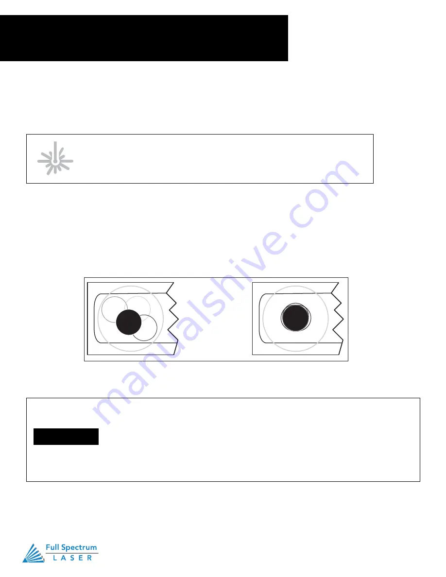
7. Check Results

: With the forth corner test fire complete, open the lid and remove the thermal

tape. The four burn marks should overlap each other perfectly (see illustration). If they do not overlap

perfectly, you will need to align the mirrors.

Figure 4.3


Not Aligned 

Aligned


PRO TIP! 

The idea is that when the laser is not aligned, you 

will have two black dots from the test fires in the top and bottom 

positions. The red laser pointer is aligned with the invisible  laser


pointer so gives you immediate feedback on the mirror adjustment. 

By adjusting it into the middle of the two black dots, you are splitting 

the error difference. Usually after 1 or 2 iterations, the black dots will 

be exactly on top and this axis is aligned. The goal is to have the two 

black dots overlap exactly.


4. Close Safety Lid: 

Safety measures should make it impossible to fire the laser with the safety lid open. 

Regardless, never attempt to fire the laser with safety lid open.

5. Test Fire the Laser:

 Press the Fire Laser Icon Button on the touch screen.

6. Repeat Test Fire in Other Three Corners: 

Without removing the thermal tape, repeat firing the laser once 

in each of the other corners of the machine (Upper Right, Lower Right, and Lower Left).

7. Check Results:

 With the forth corner test fire complete, open the lid and remove the thermal tape. The four 

burn marks should overlap each other perfectly (see illustration). If they do not overlap perfectly, you will need 

to align the mirrors.

Find and push this icon on your Muse 3D touch screen to test fire the laser.

When the laser is not aligned, you will have two black dots from the test fires in the 

top and bottom positions. The red laser pointer is aligned with the invisible laser 

pointer so gives you immediate feedback on the mirror adjustment. By adjusting it 

into the middle of the two black dots, you are splitting the error difference. Usually 

after 1 or 2 iterations, the black dots will be exactly on top and this axis is aligned. 

The goal is to have the two black dots overlap exactly.

NOTICE

Section IV. 

Tests & Adjustments

1. Alignment Test

Содержание MUSE 3D

Страница 1: ......

Страница 2: ...tions Save Controls Muse 3D Controls 2 3 4 5 6 8 9 10 11 12 13 15 19 21 22 23 24 26 36 37 38 39 41 42 42 43 45 47 View Snap Controls Drawing Controls Position Menu Section VII Operations General Funct...

Страница 3: ...rself with this manual before using your laser cutter For more information and product selection please visit www fslaser com Compliance Statement The Full Spectrum Laser MUSE 3D Laser System is a cla...

Страница 4: ...ze that it is the responsib NEVER CUT PVC polyvinyl c and potentially lethal ALWAYS have on hand a first a inhalation Be sure to store this ki Indicates a risk of fire Indicates an electrical hazard W...

Страница 5: ...ave the laser system unattended during operation Keep your laser system clean A buildup of cutting and engraving residue and debris is dangerous and can create a fire hazard Keep your laser system cle...

Страница 6: ...hine Your warranty will be void if your machine is damaged by corrosion from engraving or cutting PVC or vinyl Never engrave or cut any unknown material The vaporization melting of many materials incl...

Страница 7: ...lly organic materials such as paper can lead to increased risk of flame propagation or work piece ignition Never operate your machine unattended There is a significant risk of fire if the machine is s...

Страница 8: ...s oil finishes adhesives solvents and liquid propane for internal combustion engines Preventing the buildup of dust is one of the key means for controlling fire and explosion hazards The principal eng...

Страница 9: ...rotected from surges or short circuits POWER ON OFF is controlled by the switch at the back of the machine To power the machine on press the side down To turn power off press the o side down In case o...

Страница 10: ...Guide and the top 4 foam pieces securing the machine 4 Remove Accessories Nestled in packing foam inside the interior of the machine are the following parts and accessories a plastic bag with cords a...

Страница 11: ...t is available from 8am to 5pm PST M F at support fslaser com 12 Unpacking List Your laser shipped with the following included parts and accessories 1 Air Assist Tube 1 Focus Billet 1 Coolbox 2 Water...

Страница 12: ...Ethernet and should be the primary way of connecting B Assemble Cool Box Water System 1 Using the large rubber tubing included connect the water out on the Cool Box to the water in on the Muse Do the...

Страница 13: ...Yellow zip ties secures the laser head and x gantry during shipping Open the lid and identify all yellow zip ties 2 Cut and Remove Yellow Zip Ties Using a small pair of scissors nail cutters work rema...

Страница 14: ...of machine to ducting to exhaust fan to second ducting Now plug in the exhaust fan into the bottom power plug marked exhaust on the back of your Muse 3D machine Figure 3 3 Figure 3 4 Figure 3 5 Addit...

Страница 15: ...lly if cutting wood When accumulated debris remains over 70 after cleaning replace Pre Filter HEPA Filters Clean immediately when suction is reduced Use a shop vacuum to clean accumulated dust W clean...

Страница 16: ...s a water pump for cooling the laser tube For Coolbox users skip this step and refer to Appendix A Coolbox Assembly Coolbox users will not need a bucket Never Fire the Laser Without a correctly connec...

Страница 17: ...om 19 2 Attach Water Pump Fitting Remove the water pump from its packaging Attach the plastic fitting to the water pump by gently screwing it on Figure 3 7 3 Prep Water Bucket Fill a clean 5 gallon bu...

Страница 18: ...ure 3 9 Figure 3 10 Technical Support is available from 8am to 5pm PST M F at support fslaser com 20 4 Attach Inlet Water Tubing Push one end of one of the two 2 silicone water tubes onto the water pu...

Страница 19: ...Figure 3 11 W WA AT TE ER R O OU UT T W WA AT TE ER R I IN N Figure 3 12 Technical Support is available from 8am to 5pm PST M F at support fslaser com 21 5 Attach Outlet Water Tubing Push one end of...

Страница 20: ...zed air is critical to safe and efficient cutting operations as it not only helps cut through material more quickly but also helps prevent the formation of flames For Coolbox users skip this step and...

Страница 21: ...om 8am to 5pm PST M F at support fslaser com 23 3 Attach Air Hose to Laser Cutter Insert the other end of the black air inlet hose into the air inlet nozzle in the back of laser cutter via the barbed...

Страница 22: ...se on the power inlet to protect the machine from surges or short circuits If this fuse ever needs replacement please contact Full Spectrum Laser technical support Section III Installation Assembly 5...

Страница 23: ...ible If direct connecting to router is not available i e due to location of router then we recommend using an Ethernet to Wi Fi adapter that is connected to the router If both of those are not possibl...

Страница 24: ...the screen 4 Type IP Into Browser On the Network Screen you will see a Wired IP number Using your computer type this IP number into your favorite browser Google Chrome is recommended This will link yo...

Страница 25: ...u have installed a new laser tube you must align the laser using the procedure provided For this alignment test we will test fire the laser once in each corner of the machine to make sure the laser is...

Страница 26: ...firing the laser once in each of the other corners of the machine Upper Right Lower Right and Lower Left 7 Check Results With the forth corner test fire complete open the lid and remove the thermal t...

Страница 27: ...3 X Gantry 5 Stages 1 PREP 2 ALIGN LASER OUTPUT TO MIRROR 1 3 ALIGN MIRROR 1 TO MIRROR 2 4 ALIGN MIRROR 2 TO MIRROR 3 5 FOCUS LENS ALIGNMENT Tools Needed THERMAL PAPER 2 5 MM HEX WRENCH Section IV Tes...

Страница 28: ...can also direct print to the software Each opera system does this in a slightly different way so check the instructions for your p computer Figure 7 2 Before starting any project be sure you are awar...

Страница 29: ...D Figure 4 6 1 Open the Safety Lid You will need to access the interior of the machine 2 Place Thermal Paper Take a small piece of thermal paper approx 15 mm should be plenty and place it firmly over...

Страница 30: ...ition the red dot exactly over the burn mark Do not worry if this places the red dot away from the center of the mirror we will adjust to center in the next step Stage 3 Align Mirror 1 to Mirror 2 Sec...

Страница 31: ...Aligned Check your results by repeating this process until the two burn marks are both center and perfectly overlapping each other Once aligned you will repeat this procedure on the next mirror 7 Repo...

Страница 32: ...lid open 6 Test Fire the Laser Press the Fire Laser Icon button on the touch screen You may need to fire the laser twice to see the burn mark on the thermal paper Section IV Tests Adjustments 2 Mirror...

Страница 33: ...diode to move the burn mark over the red beam 11 Repeat Until Aligned Check your results by repeating this process until the two burn marks are both center and perfectly overlapping each other 7 Adjus...

Страница 34: ...om of the laser head assembly The default lens for Muse is 2 0 The following lenses are compatible with Muse 3D 1 0 2 0 2 5 and 5 0 37 nical Support is available from 8am to 5pm PST M F at support fsl...

Страница 35: ...before accessing the power supply Focusing Focal Lens Close up To install lens simply slide lens fitting into holder 38 Technical Support is available from 8am to 5pm PST M F at support fslaser com 89...

Страница 36: ...ully read all instructions before beginning the replacement procedure as there are several critical steps which must be properly followed to avoid breaking the laser tube The included pictures show ho...

Страница 37: ...nt of the current project Locked Unlocked Lock or unlock the gantry for auto or manual homing Test Fire Test fire the laser Used for mirror alignment and testing Camera Capture Captures the laser bed...

Страница 38: ...nical Support is available from 8am to 5pm PST M F at support fslaser com 41 Safety Override Lid Failsafe As a safety feature the lid has a magnetic failsafe that disconnects the laser when the lid is...

Страница 39: ...com 42 Safety Override Waterflow Failsafe The laser will not fire unless water is flowing through the laser tube The following indicator informs Muse 3D operators if water is not flowing Figure 5 4 F...

Страница 40: ...tart Run selected Project Technical Support is available from 8am to 5pm PST M F at support fslaser com 43 Job History Screen There are many accessible sub screens for Muse s touch screen Each is deta...

Страница 41: ...Tools sub screen Factory Reset Resets to factory settings Camera Calibration Begin camera Figure 5 9 ABOUT SUB SCREEN Model Indicates Laser Model Firmware Version Current Version of Touchscreen Sectio...

Страница 42: ...e from 8am to 5pm PST M F at support fslaser com 46 Lock Unlock Indicator Figure 5 12 LOCKED ICON Indicates the gantry is locked When locked user must move gantry using JOG controls Figure 5 13 UNLOCK...

Страница 43: ...er Engraving Parameters G Project Info H Video Feed I Jog Controls J Sync Indicator F Status Indicators Z Settings B Projects C Layers Objects D Indicator E Position Menu n Menu Menu A File New Projec...

Страница 44: ...creen are deselected Invert Selection Ctrl I Items previously selected are now unselected and items unselected are selected Select by Font Type Select item by font type Settings Displays settings menu...

Страница 45: ...nto a single compound shape Path Join Paths Ctrl J Combine 2 or more selected paths into one compound path Split Paths Shift Ctrl J Split a compound path into its original separate paths Convert to Pa...

Страница 46: ...feature Snap to Grid Enable or disable the Snap to Grid feature Snap to GuideLines Enable or disable the Snap to GuideLines feature Snap to Full Pixels Enable or disable the Snap to Full Pixels featur...

Страница 47: ...ion you will be introduced to the major interface features of RetinaEngrave v3 0 Figure 6 1 Technical Support is available 8am 5pm PST Monday Friday support fslaser com 702 802 3103 46 Settings B Lase...

Страница 48: ...le 8am 5pm PST Monday Friday support fslaser com 702 802 3103 47 Editor Network Settings B Save Save project Undo Reverse your last action Redo Reverse your last undo Muse Control q Capture Workspace...

Страница 49: ...wing tool Rectangle Create a rectangle with the drawing tool Ellipse E Create an ellipse with the drawing tool Polygon Create a polygon with the drawing tool Triangle Create a triangle with the drawin...

Страница 50: ...Rotate object 90 right Group Menu Group Group objects Merge Union Combine layers into a single compound layer Difference Combine non overlapping layers into a single compound layer Intersection Combin...

Страница 51: ...s Sets unit of measurement to millimeters Inches Sets unit of measurement to inches Picas Sets unit of measurement to picas Points Sets unit of measurement to points Grid Toggles grid on off isometric...

Страница 52: ...er radius from 0 to 30 Edge Adjust edge enhancement threshold from 0 to 30 Threshold Apply Threshold adjust from 0 to 255 Invert Reverse Black and White elements Power Select power percentage from 1 t...

Страница 53: ...hite threshold from 0 to 255 Indicators Bottom Row Position Indicator Displays current position of the laser on the grid Time Remaining Indicator Displays the time remaining to complete the current jo...

Страница 54: ...Raster Properties will automatically open For vector objects basic shapes it will open up the Vector Fill Rasterize tap Select the icon next to Rasterize to open the Raster Properties Setting Passes T...

Страница 55: ...ll open on the right side For vector engravings this tab will allow you to set the infill for the object Infill This section fills in the selected object The way the fill will appear is based on which...

Страница 56: ...eper engravings while higher pulse rates result in shallower marks Wobble Widens the beam path by running vectors along concentric circles Amplitude Affects the diameter of the wobble Bigger amplitude...

Страница 57: ...he software itself Here you can design and create objects without accessing third party design software Adding Text Click the T icon and then click anywhere in the view window You can now write your t...

Страница 58: ...selected text Apply Click to apply all transform changes Text Transform Options Transform options allow the operator to alter the shape and skew of text Text Appearance Transform options allow the op...

Страница 59: ...ndividual paths For all other types of layers a new path is created preserving any transforms The user creates a text layer then converts to a path Because the text was comprised of more than one dist...

Страница 60: ...fferent options as follows Line L Closed Autoscale Corners Rectangle R Round Create rounded corners Round2 Create inverted rounded corners Bevel Create beveled corners Inset Create inset corners Fancy...

Страница 61: ...elected layer where the other selected layers do not overlap For example users can create an ellipse and subtract a rectangular area so the ellipse can be placed over another layer and not obstruct pa...

Страница 62: ...ere joined The user joins together multiple path objects so that they can be transformed more easily and change their properties as a single object Split Paths Shift Ctrl J Split a compound path into...

Страница 63: ...old your mouse over one of the four corner resizing nodes By moving the mouse you can to rotate the object from the opposing node E Home to Location Instantly home the laser to any location in the wor...

Страница 64: ...black pixel or laser dot is the result of the laser turning on and firing at that location This location is controlled by the input image which can be thought of as a Section VII Operations General Fu...

Страница 65: ...to drag n drop it directly into the workspace window If there are ever any problems importing files in this manner direct printing a converted PDF file is the next method to try Most design software h...

Страница 66: ...hould be created with laser cutting considered 4 Place Material Place your material into the laser bed workspace 3 Import Design Create your design in the program of your choice Note Files should be c...

Страница 67: ...ny design software will work You can choose the software you are most comfortable with as long as you can convert files to PDF which most can You can also direct print to the software Each operating s...

Страница 68: ...components of any material used and the limitations of utilizing that material thickness chemical residues etc with a 45W laser tube Always check with the material manufacturer or MSDSonline com if t...

Страница 69: ...100 is ideal Lowering the speed will allow you to create deeper engravings as it allows the laser beam to be in contact with the material for a longer period of time Section VII Operations Engraving E...

Страница 70: ...r photorealistic engravings To 3D engrave an object click the 3D engraving button You can then adjust the 3D engraving with the Blur Edge and Intensity slide bars PHOTO ENGRAVING EXAMPLE Applying B W...

Страница 71: ...ects are then processed from top to bottom Setting Vector Power Power will determine how much power the laser tube delivers As with speed power will vary depending on the wattage of the laser tube and...

Страница 72: ...opposed to fill parts of the pattern for a second design option Again we will instruct the laser using our vector properties In this design the blue lines will not be cut through on our material but i...

Страница 73: ...8am to 5pm PST M F at support fslaser com 72 Designing with RetinaEngrave v3 0 RetinaEngrave v3 0 contains design tools to allow for custom designs within the software itself Here you can design and c...

Страница 74: ...n width and height Rotate Rotate text a set number of degrees up or down Skew Skew the angle of text by a set number of degrees on the X and Y axis Copies Create duplicates of the selected text Apply...

Страница 75: ...import differences With Convert to Raw Path new path objects are always created regardless of the type the original layer and transforms are preserved The user creates a text layer then attaches it to...

Страница 76: ...rounded corners Round2 Create inverted rounded corners Bevel Create beveled corners Inset Create inset corners Fancy Create fancy corners Autoscale Corners Toggle autoscale corners on and off Uniform...

Страница 77: ...r another layer and not obstruct part of it Or use to make a design that is made up of standard shapes by subtracting certain areas Create Compound Shape Difference Combine non overlapping layers into...

Страница 78: ...d change their properties as a single object Split Paths Shift Ctrl J Split a compound path into its original separate paths The result is a path layer for each separate path in the Compound path Simp...

Страница 79: ...ir properties as a single object Split Paths Shift Ctrl J Split a compound path into its original separate paths The result is a path layer for each separate path in the Compound path Simplify Path Ct...

Страница 80: ...n workspace to move the laser head To use the jog feature the laser head must be in the Locked position To lock the laser head push the Lock icon so that the icon has a closed lock icon Positioning Ma...

Страница 81: ...power cord of the main Muse 3D unit This should be a last resort method for emergencies as the other methods are quicker to access and prevent pulling on cords and connections Section VII Operations...

Страница 82: ...ny location in the work bed by simultaneously holding the Ctrl key and left clicking the mouse This allows you to choose where the laser starts the job Mouse Controls Resize Rotate Home to Location Se...

Страница 83: ...eady to run your job To double check a position on your workspace CTRL Click anywhere on the work space to position the laser head there Section VII Operations Camera Capture Workspace 1 Place materia...

Страница 84: ...hey should appear in the Object Manager box Delete data not needed If just engraving delete vector data if just cutting or marking delete bitmap data 6 You are now ready to run your job Tape Section V...

Страница 85: ...le tips to keep your camera clean and functioning at peak performance Just like with mirrors you will need to clean the camera lens periodically Use lens wipes to gently clean the camera lens as neede...

Страница 86: ...space Avoid opening the lid during the calibra process This process should take about 5 minutes 8 Select Camera Calibration Touch the Camera Calibration button under the tools tab a select Stitch Cal...

Страница 87: ...terials will still have wide variance in power current and speed settings depending on the properties of that material such as density and thickness For example wood can be soft pine or hard oak depen...

Страница 88: ...ning the replacement procedure as there are several critical steps which must be properly followed to avoid breaking the laser tube The included pictures show how to properly connect wires to the tube...

Страница 89: ...ne 10 Re Attach Tube Retainer Straps Gentle place the tube restraining straps back into position over the rubber holders and secure the new laser tube in place 11 Re Thread Hex Nuts Carefully re threa...

Страница 90: ...belt Pull on the Y idler pulley mount with your hand Moderate to strong forceis recommended If the motors do not jog verify that the motors are connected to the control card Section VIII Hardware Mai...

Страница 91: ...ne lace new air assist cone under focus lens and into slot Tighten set screw with a 1 5 ex wrench Reattach air hose lide the current focus lens out of the slot This does not require tools lide new len...

Страница 92: ...from the catch tray of the machine Less excess material will reduce fire risk and provide for better exhausting Always keep rails motors and moving parts free from excess material as it can obscure mo...

Страница 93: ...to 4 Pin Terminal Connector 1 and a small plastic bag containing 2mm Hex Key 1 2 5mm Hex Key 1 5 5 7mm Wrench 1 two M3 Nuts 2 and four Acorn Nuts 4 4 Remove Coolbox Start by removing the three pieces...

Страница 94: ...m your existing air pump Do not disconnect the other end of the air assist hole from your Muse 3D Next attach the air assist hose to the Air Out port on your Coolbox 8 Connect Exhaust Fan to Coolbox U...

Страница 95: ...he Muse exhaust port 2 Attach with 4 ducting to flange side of exhaust fan then the second ducting to the exit port of the exhaust fan 3 Ventilate the ducting outside through a window or exhaust port...

Страница 96: ...ition to engrave on your workpiece The red dot should be in the same vertical X Z plane as the center axis of the workpiece NOTICE Appendix B Rotary Attachment Installation he Full Spectrum Laser Hobb...

Страница 97: ...ct It is crucial that the rotary be level Use a small carpenter s level to be sure your rotary is flat within the interior of the laser cutter Appendix B Rotary Attachment Using the Rotary Attachment...

Страница 98: ...us Lens If you are requiring finer engraving and thinner cutting such as fonts below 8pts we recommend the 2 lens The 2 lens has a good combination of fine engraving and thin cutting A short focus len...

Страница 99: ...ately and the Hobby Lasers had a 60 day base warranty on all items excluding shipping unless an extended warranty was purchased After 8 7 2012 the Hobby lasers have a 60 day warranty on all items and...

Страница 100: ...in the industry Contact us if you have any questions or issues with your Muse 3D Laser Cutter We can also offer convenient purchasing of accessory upgrades and replacement of consumable items Refer t...

Страница 101: ...ss the country going to conventions and maker events or just check out all the awesome stuff we make Best of all we offer all those designs for all those projects we make with our laser cutters and 3D...

Страница 102: ...rade with Pro Series by Full Spectrum Laser Our Pro Series C02 and Fiber Laser Cutters take your production to the next level Industrial grade components give you faster movement better precision and...

Отзывы: