CHAPTER 5
Extension Configuration
Installing Power, Ground, and Alarm Cables
FNC-7500-0061-200
Issue 1, May 2009
FLASHWAVE 7500 Release 6.1
Equipment Installation
5-38
Fujitsu and Fujitsu Customer Use Only
Install Shelf Power Harnesses CB2
15
Refer to the cabling schematic (identified in
. Is a
shelf to be connected to circuit breaker 2 (CB2)?
If YES:
If NO:
16
Locate the rack/shelf power harness (HA15B-0001-C413,
) for the shelf.
Note:
The length of the cables may be altered at the discretion of the installer to ensure proper
length.
17
Prepare the power leads by installing the terminal lugs (wrapped in a plastic bag shipped with
the cable) that are required on one end of the cable (see
). Ensure that no
wire strands are shorting terminals together and that leads are securely fastened. The cable
should now have terminal lugs on both ends of the power cable.
Note:
The shelf power wiring is the same with all rack configurations. Observe the color coding of the
power cable.
18
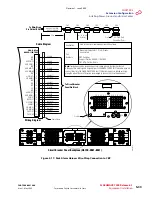
On the backplane of the shelf identified in
, remove the plastic cover on the
shelf power terminal strip located on the bottom right of the shelf backplane (
).
19
Connect both ends of cable GA of the power harness as follows:
a.
Identify lug GA in the power harness (see
) and connect it to shelf
b.
Connect the other end of the same cable to CBP terminal RTN A1 CB2 (see
).
20
Connect both ends of cable GB of the power harness as follows:
a.
Identify lug GB in the power harness (see
).
b.
Connect the other end of the same cable to CBP terminal RTN B1 CB2 (see
).
Revision 1, June 2009
Содержание FLASHWAVE 7500
Страница 8: ...Revision 1 June 2009 ...
Страница 10: ...Revision 1 June 2009 ...
Страница 16: ...Revision 1 June 2009 ...
Страница 362: ...Revision 1 June 2009 ...
Страница 386: ...Revision 1 June 2009 ...


