CHAPTER 5
Extension Configuration
Installing the Rack
5-9
FLASHWAVE 7500 Release 6.1
Equipment Installation
Fujitsu and Fujitsu Customer Use Only
FNC-7500-0061-200
Issue 1, May 2009
shows an
example
mounting diagram. Mounting diagrams will vary
depending on equipment and location.
4
Using a punch and hammer, mark the position where the holes are to be drilled.
5
Determine the type of floor anchor to be used.
6
Is the floor anchor for a concrete floor?
If YES:
.
If NO:
7
In accordance with the dimensions of the anchor to be used, drill the holes in the concrete
floor.
8
Clean the drill shavings from the holes.
9
Install an anchor in each of the holes.
10
Remove any debris from the area in which the rack will be mounted.
11
Move the rack into position, aligning each of the holes in the base of the rack to the anchors.
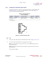
Figure 5-3: Example Diagram—7 feet x 23 inch Equipment Rack Floor Dimensions
25.94
1.76
R0.50
R0.83
45°
5.24
4.79
21.50
2.17
4.19
5.11
1.51
Note:
All Dimensions are in inches.
m1718g
d_
1
Revision 1, June 2009
Содержание FLASHWAVE 7500
Страница 8: ...Revision 1 June 2009 ...
Страница 10: ...Revision 1 June 2009 ...
Страница 16: ...Revision 1 June 2009 ...
Страница 362: ...Revision 1 June 2009 ...
Страница 386: ...Revision 1 June 2009 ...


