CHAPTER 5
Extension Configuration
Checking Power at Extension Shelf
FNC-7500-0061-200
Issue 1, May 2009
FLASHWAVE 7500 Release 6.1
Equipment Installation
5-44
Fujitsu and Fujitsu Customer Use Only
4
Is the DMM measurement between –40 and –57 V DC?
If YES:
If NO:
Report as a trouble item to the installation group and repeat voltage checks after the trouble is
corrected.
5
Connect the negative DMM test lead to the GB ground terminal on the rear-panel power
strip, and connect the positive DMM test lead to the MAIN B voltage terminal. If required,
record the test results for future reference.
6
Is the DMM measurement between –40 and –57 V DC?
If YES:
If NO:
Report as a trouble item to the installation group and repeat voltage checks after trouble is
corrected.
7
Reinstall the plastic cover over the power strip on the shelf backplane.
8
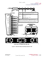
At the front of the Extension shelf, locate the front-panel voltage test points (see
), connect the negative DMM test lead to the G (ground) test point, and connect the
positive DMM test lead to the MAIN A test point.
Figure 5-20: Front-Panel Voltage Test Points (Extension Shelf)
(Extension Configuration)
TERM2
TERM1
SYNC
ABN
ACO
LAMP TST
PWR
B
A
MN
MJ
CR
MAIN
A
B
G
m1656x
a_
2
Revision 1, June 2009
Содержание FLASHWAVE 7500
Страница 8: ...Revision 1 June 2009 ...
Страница 10: ...Revision 1 June 2009 ...
Страница 16: ...Revision 1 June 2009 ...
Страница 362: ...Revision 1 June 2009 ...
Страница 386: ...Revision 1 June 2009 ...


