background image

va04.3_001g_Eng.fm

33

Main

tena

nce pr

éven

tive

4.4  Checks

A quality control certificate is available at the end of this section.

In order to ensure the smooth running of the checking procedure, recharge the 
battery for 16 hours beforehand. 

4.4.1 Accessing the tests

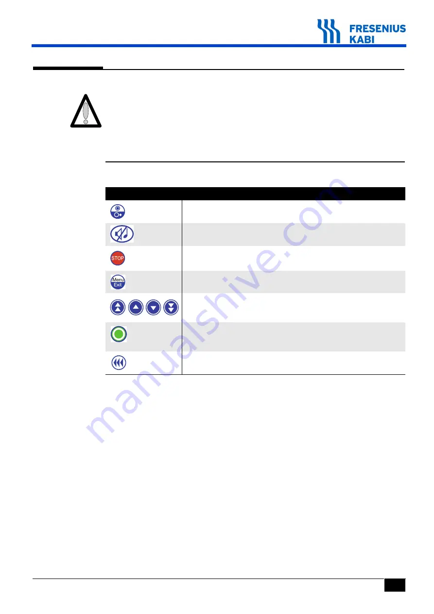
Keyboard description.

Key

Function

ON

 switches on the pump.

OFF

 switches it off when pressed for over three seconds.

SILENCE ALARM

STOP

 stops infusion.

MENU/EXIT

 accesses the test mode.

The selection keys scroll through the numbers and letters on the 
tenths, units and tens values and allow one to move to the next 
menu.

OK

 validates your test selection or moves the cursor. 

enter

 starts up infusion.

exit

 exits the screen and returns to the "previous" menu. 

Bolus or purge

Maintenance préventive

Содержание Volumat Agilia

Страница 1: ...0 9 C E S Volumat Agilia Technical Manual ...

Страница 2: ...te test are added Jan 12th 2015 5 Index f The torque value to re assemble the OCS clamp motor is added in the intervention procedure no 11 Feb 24th 2017 6 Index g 4 3 Training is added and a reference to it is mentioned in each intervention procedure in Maintenance level 4 4 25 Electrical safety test standards are modified in the corresponding section and in the quality control certificate 4 7 upd...

Страница 3: ...s board 23 2 1 5 The air detection board 24 2 2 Operational description 25 2 2 1 Administration set check and maintenance sub assembly 25 2 2 2 Pumping sub assembly 25 2 2 3 External connections sub assembly 25 3 Description of the menus 27 3 1 Options menu 27 3 2 Calibration menu 28 3 3 After Sales Service test menu 28 3 4 Maintenance options menu 29 4 Preventive maintenance 31 4 1 Recommendation...

Страница 4: ...peration check 48 4 4 24 Battery life check 49 4 4 25 Electrical test 49 4 5 Maintenance options 50 4 5 1 Access to test 50 4 5 2 SAV 1 Maintenance date 51 4 5 3 SAV 2 Initial set up 51 4 5 4 SAV 3 Data log event 52 4 5 5 Quality Control Certificate 53 4 6 Flow rate check 55 4 6 1 Measuring by computer 55 4 6 2 Measuring with a scale 58 4 6 3 Measuring with a test tube 60 4 7 Cleaning and disinfec...

Страница 5: ... Procedure N 10 Pressure sensor 117 Procedure N 11 OCS clamp motor 123 7 Calibrations 127 7 1 Calibrations procedure 127 7 1 1 Access to the calibrations 127 7 1 2 Etal 1 Pressures 129 7 1 3 Etal 2 Door 131 7 1 4 Etal 3 Air sensor 132 7 1 5 Elal 4 Flow rate 133 8 Spare parts catalogue 135 ...

Страница 6: ...66 TM_Volumat_Agilia_Eng_TDM fm ...

Страница 7: ...nd reduces the time needed for training and maintenance Volumat Agilia can be programmed in three different modes No drug name Drug labelling Vigilant Drug Lib The drop detector is optional Volumat Agilia has got a patented auto test called OCS test Occlusivity Check System that checks the correct working order of the pump in association with its administration set thus preventing any risk of free...

Страница 8: ...8 va01_001e_Eng fm Introduction 1 2 Operation diagram ...

Страница 9: ...sted on the tubing packaging Check that the prescriptions are compatible with the characteristics of the trumpet curves and with the occlusion alarm setting times in relation to the programmed flow rate The device uses a Lithium Ion rechargeable battery Incorrect handling of a Lithium Ion battery by a non qualified personnel may cause leakage heat smoke explosion or fire which could result in dete...

Страница 10: ...ls Dimensions H x W x D 135 x 190 x 170mm Weight 2 Kg 1 5 4 Material characteristics Components Materials 1 Screw cap 2 Polyamide 2 Nut bolt button Polyamide 3 M8 moulded screws Polyamide 4 Angle bracket ABS 5 Battery door ABS 6 Right and left flanges Polycarbonate 7 Pumping block plate Polyamide 8 Moulded cover over light guide ABS 9 Light guide Polycarbonate 10 Window Polycarbonate 11 Moulded ba...

Страница 11: ...e and manufacturer s declaration on EMC section of the Instructions For Use 22 Air detector support ABS 23 Door ABS 24 Door plate Polyarylamide 25 Moulded lever hooks Polyarylamide 26 Right and left door hinge Polyamide 6 27 OCS fuse Polyacetal 28 OCS unclamping finger Polyamide 29 Mechanical spring cap Polyamide 30 OCS detector cradle Polyarylamide 31 Pumping block Polyamide 32 Star motor ring Po...

Страница 12: ...12 va01_001e_Eng fm Introduction ...

Страница 13: ...tector Angle bracket Volumat Agilia pump is made up of 3 main parts an angle bracket a cover and a base The cover contains a display board The base supports a CPU board an air bubble detector board an OCS system a pump motor mechanism an air bubble detection a clamp system The angle bracket supports a power supply board a mains board a battery ...

Страница 14: ...ted to the other parts by means of connectors J1 connector to keyboard Pin Signal Description 1 A_LED Ground 2 COL0 Keyboard column 0 3 COL1 Keyboard column 1 4 COL2 Keyboard column 2 5 LIG0 Keyboard line 0 6 LIG1 Keyboard line 1 7 LIG2 Keyboard line 2 8 ON OFF Keyboard ON OFF key 9 CTR Keyboard control or line 3 10 GND Ground J2 connector to CPU board Pin Signal Description A1 GND Ground B1 VBAT ...

Страница 15: ...ery power supply or 10Vmains B13 GND Ground J3 to display connector Pin Description 1 A_LED Backlight LED anode 2 C_LED Backlight LED cathode 3 Not connected 4 Not connected 5 GND Ground indicating serial access to LCD 6 MOSI LCD serial data line 7 CLK LCD serial line clock 8 GND Not used by the LCD in serial access 9 GND Not used by the LCD in serial access 10 GND Not used by the LCD in serial ac...

Страница 16: ...onous or non synchronous serial link optional Bluetooth connection The CPU board is connected to the display board by means of the J2 connector A ribbon cable connects it to the power supply board by means of the J14 connector J2 J7 J4 on the inside J11 J12 J14 J9 J1 J13 J3 J10 J1 connector to pumping motor Pin Description 1 BOBINEA motor A coil 2 BOBINEA motor A coil 3 BOBINEB motor B coil 4 BOBI...

Страница 17: ...e 6 GND Ground J7 to CLAMP connector board Pin Description 1 GND Ground 2 MC_OPTO2 Opto 2 status 3 MC_CD_OPTO Opto 2 power supply 4 GND Ground 5 MC_OPTO1 Opto 1 status 6 MC_CD_OPTO Opto 1 power supply 7 GND Ground 8 S_CLAMP CLAMP opto status 9 S_CD_CLAMP CLAMP opto power supply 10 GND Ground J9 to JTAG connector micro programming Pin Description 1 3V3 3 3V power supply 2 3V3 3 3V power supply 3 TC...

Страница 18: ...nal A6 GND Ground B6 CLK SPI bus clock signal A7 GND Ground B7 RESET Control signal A8 RSLCD Control signal intended for LCD display B8 CSLCD Control signal A9 CSLDCD Control signal B9 CD_BUZ_AFF Buzzer command A10 GND Ground B10 S_ANA_DOOR Analogue signal sent by the DOOR sensor A11 3V3 Power supply 3 3V B11 GND Ground A12 Not connected B12 PRES_CARTES Diagnostic signal correct board connection A...

Страница 19: ...date stamper B2 Not connected A3 GND Ground B3 3V3 3 3V power supply A4 TON OFF Keyboard ON OFF key B4 GND Ground A5 SCL_ALIM I C bus clock signal between main micro controller CPU and secondary Power supply B5 SDA_ALIM I C data signal between main micro controller CPU and Power supply A6 GND Ground B6 RXIR Infrared cell reception signal A7 TXIR Infrared cell emission signal B7 GND Ground A8 SCK S...

Страница 20: ...ted on the angle bracket It is used to supply power to the electronic unit from the 100V 240VCA network or externally from 9VCC It also charges a 2 2Ah battery J6 J3 on the inside J1 circular J2 on the inside J4 on the inside connector Power supply board This board is connected to the other parts by means of connectors J1 to CPU board connector Pin Description A1 GND Ground B1 VBAT Battery power s...

Страница 21: ...BATTERIE Battery 2 ANA_CTN CTN 3 GND Ground battery and CTN reference B5 SDA_ALIM Signal Data of the I C bus data signal between main CPU and secondary Power supply micro controller A6 GND Ground B6 RXIR Infrared cell reception signal A7 TXIR Infrared cell emission signal B7 GND Ground A8 SCK Serial bus clock signal B8 GND Ground A9 RXD External plug data reception signal B9 TXD External plug data...

Страница 22: ...nection data emission 3 RXD Serial connection data reception 4 5V Power supply accessories supplied by the board 5 GND Ground 6 RELAIS Relay command open collector 7 GND Ground 8 10V0 External power supply supplied by the board 9 GND Ground 10 GND Ground 22 va02_001e_Eng fm Description and operation ...

Страница 23: ...le bracket It enables the power supply board to be changed without the need for soldering J1 on the inside F2 F1 J2 Mains board This board is connected to the other parts by means of connectors J1 connector to power supply board connector Pin Signal Description 1 Neutral Mains power supply 2 Phase Mains power supply 3 GND Ground J2 connector to mains Pin Signal Description 1 Neutral Mains power su...

Страница 24: ...ection board This board is connected to the other parts by means of connectors J1 to CPU board connector Pin Description 1 GND Ground 2 DA_ANA_AIR Analogue signal sent by the air detector 3 GND Ground 4 DA_DISCH Air detector command reset 5 3V3 3 3V power supply 6 DA_GAIN Air detector adjustment gain command 7 3V3 3 3V power supply 8 DA_SCL I C bus clock signal between main micro controller and ai...

Страница 25: ...he administration set 2 2 2 Pumping sub assembly The pumping sub assembly contains the peristaltic pumping mechanism The mechanism is made up of a camshaft that creates a wave like movement in a bank of 12 fingers The displacement of these fingers is controlled by the CPU board while turning it displaces the liquid at the programmed flow rate The camshaft is driven by a stepper motor and a reducti...

Страница 26: ...26 va02_001e_Eng fm Description and operation ...

Страница 27: ...ng options menu is displayed User Service Maintenance Each menu is made up of sub menus The sub menus can be accessed by using the ENTER key To access some of the sub menus you need to type in an access code This code can be defined and or de activated in the Service mode As long as the device is kept switched on the code does not need to be keyed in again Main Menu Key in code Sub menu Sub menu U...

Страница 28: ... out on the Volumat Agilia to confirm that it is operating correctly See section Checks The After Sales Service tests can also be carried out more quickly and simply from a PC using our maintenance software Contact our Technical Service for more details The After Sales Service test menu contains a series of tests or checks Test 1 Identification Test 2 Maintenance Test 3 Maintenance messages Test 4...

Страница 29: ...1e_Eng fm 29 Description of the menus 3 4 Maintenance options menu Maintenance options menu allows to enter parameters for the 3 following options SAV 1 Maintenance date SAV 2 Initial set up SAV 3 Data log event ...

Страница 30: ...30 va03 1_001e_Eng fm Description of the menus ...

Страница 31: ...the battery replacing the membrane should be carried out by a qualified technician Any abnormal functioning or failure must be reported to the qualified technical staff in your organisation or to our Technical Service In these instances the pump should not be used Important If these maintenance procedures are not observed the pump s correct operation will be impaired 4 2 2 Quality control At the r...

Страница 32: ...of maintenance does not need an extensive inventory Level 2 is intended to a technician specialized in maintenance performed through specific tools and procedures Good mechanical and electronics knowledge Two years experience minimum in a biomedical department Level 3 is intended to a technician specialized in repair performed in the maintenance department using specific tools procedures as well a...

Страница 33: ...scription Key Function ON switches on the pump OFF switches it off when pressed for over three seconds SILENCE ALARM STOP stops infusion MENU EXIT accesses the test mode The selection keys scroll through the numbers and letters on the tenths units and tens values and allow one to move to the next menu OK validates your test selection or moves the cursor enter starts up infusion exit exits the scre...

Страница 34: ...election keys Press enter to confirm The Maintenance menu displays Key in the code Press OK to confirm Choose the Test menu using the selection keys Press enter to confirm Navigate through this sub menu using the central selection keys You may exit the configuration mode at any time by pressing MENU EXIT this function cancels the modifications 4 4 2 Visual check Check the general appearance of the...

Страница 35: ...lection keys device information device name version revision and software production date device code and product serial number serial numbers CPU board serial number power supply board serial number language information language name version and revision date the language file was created zone information zone parameter number version and revision date the parameter file was created date of the l...

Страница 36: ...nu displays Scroll through the information using the selection keys Choose between the proposed options Reset or Exit RAZ using the left selection key The following Maintenance menu displays For this menu Running time the number of operating hours is reset to 0 Date the date of the last maintenance is reset to the day s date Total running time the total running time since the beginning remains inc...

Страница 37: ...n to screen using the selection keys Press exit to return to the Test menu It is necessary to use Product maintenance software to write messages in Test 3 4 4 6 Test 4 Events This test displays the list of the alarms stamped with date and time Test 4 press enter The Events main menu displays Scroll through the information from screen to screen using the selection keys Press enter to display the al...

Страница 38: ...set in LSB Date Number Date and number of calibration Select exit to return to the Test menu Refer to section 7 Calibration Calibration procedure Etal 1 pressure if one of the values is out of range 4 4 8 Test 6 Downstream pressure This test displays the downstream pressure value in mV the calibration values for the different downstream pressures in mV the date and calibration counter Test 6 press...

Страница 39: ...the calibration values in mV the date and calibration counter Test 7 press enter The main menu Door displays Scroll through the information from screen to screen using the selection keys Conversion State Door open calibration value in mV Intermediary door calibration value in mV Door closed calibration value in mV Date Number Calibration date Number of calibrations Select exit to return to the Tes...

Страница 40: ...ns that appear Select Clear to reset to 0 after all battery replacements Clear using the left selection key The Battery Info menu displays Duration the number of battery operating hours is reset to 0 resetting the number of cycles to 0 Cycles the number of cycles is reset to 0 Start date Only the total battery running time since the beginning remains incremented Scroll through the information from...

Страница 41: ...ED LCD and the two buzzer tones are functioning correctly exit exits the screen and returns to the Test menu for the entire duration of the test 4 4 12 Test 10 Keyboard This test checks that the keyboard is functioning correctly Test 10 press enter The Keyboard main menu displays Press all the keys one by one for example Press Bolus Purge the corresponding circle on the screen becomes dark Press t...

Страница 42: ...hoice using the single arrow selection keys Press OK to confirm and move to the next step Steps numbers or turns number Content or value lying between 1 and 9999 Modify the value using the single arrow selection keys Press OK to confirm and move to the next step Current high low auto or error Modify the value using the single arrow selection keys Press OK to confirm and move to the next step Press...

Страница 43: ...battery is replaced all the parameters on test 8 must be reset to zero 4 4 15 Test 13 Battery test This test discharges the battery completely and measures the time taken for the alarms and pre alarms to be triggered as well as the duration of the power cut Test 13 press enter If the pump is connected to the mains the Battery test Disconnect mains menu displays Carrying out the battery test does n...

Страница 44: ...reen using the selection keys Conversion State water air Air sensor value in mV Calibration without administration set in mV Calibration with administration set and air in mV Calibration with administration set and water in mV Frequency during calibration Frequency shift variance Date Number Date and number of calibrations Press exit to return to the Test menu Refer to section 7 Calibration Calibr...

Страница 45: ... keys Press OK to validate and move to the next step Frequency Auto or a value lying between 10 and 500 Hz Modify the value using the single arrow selection keys Press OK to validate and start up the test The Clamp motor menu displays The displacement mode and the motor position for the motor command appear at the top of the screen The number of steps decreases according to the actual change for t...

Страница 46: ...of 25 ml to warm up the administration set Test 16 press enter The Flow rate main menu displays The default values are Flow rate 100ml h Volume 25ml Duration 0h15 The IS flow rate software dedicated to this procedure is available from Fresenius Kabi Any flow rate test using the default values menu with a minimum maximum volume indication is facilitating the checking of the result obtained when thi...

Страница 47: ... Press exit to return to the Test menu 4 4 20 Test 18 Occlusivity This test is dedicated exclusively to product development 4 4 21 Test 19 Clamp This test displays the presence or absence of the administration set clamp and its position Test 19 press enter The main Clamp menu displays Clamp checking test 19 Door open without administration set check Clamp absent Position open Insert the tube clamp...

Страница 48: ...tainer Start the infusion and leave it running for 30 seconds Position the 3 way stopcok on the manometer side Check that the alarm is triggered for a value of 1bar 0 15 bar Stop the infusion cycle by pressing STOP When the value of the measured pressure lies outside of the limit selected recalibrate the pressure sensors see Etal 1 Upstream and downstream pressure sensors calibration 4 4 23 Mains ...

Страница 49: ...See test 12 Battery life When the test has been carried ou automatically as described in test 13 the battery life must be greater than 6 30 hours When the test is carried out in normal functioning mode the battery life must be an average of 8h for a flow rate of 125ml h 4 4 25 Electrical test Carry out the electrical test according to IEC 60601 1 or IEC 62353 standard For further information pleas...

Страница 50: ...starts up infusion exit exits the screen and returns to the preceding menu Moving to the Maintenance mode Press MENU EXIT Keep it pressed down while pressing ON When the Options main menu displays deselect MENU EXIT and ON Select Maintenance menu using the selection keys Press enter to confirm The Maintenance menu displays Key in the code Press OK to confirm Choose the Maintenance options menu usi...

Страница 51: ...confirm and move to the next step Modify the month using the selection keys increase and decrease using the single arrows press the downward double arrow for a Clear month Press OK to confirm and move to the next step Proceed as above to modify the year Press OK to confirm 4 5 3 SAV 2 Initial set up This screen activates the initial configuration when the device is next switched on The Initial set...

Страница 52: ...is test displays the list of the alarms stamped with date and time like Test 4 The Data log event main menu displays Scroll through the information from screen to screen using the selection keys Press enter to display the alarm type Press MENU EXIT to return to the Test menu ...

Страница 53: ...L1 pressure calibration if one of the values is out of range 4 Check the downstream pressure Install the water manometer at the administration set outlet Set the pressure threshold at 750mmHg Start infusion at 100ml h Check that the Downstream occlusion alarm is triggered at 750mmHg 125 1bar 0 15 Refer to section 7 Calibration Calibration procedure EtAL1 pressure calibration if one of the values i...

Страница 54: ...ssage clamp absent position opened Insert the tube and close the door Check the message clamp present position closed 13 Check the flow rate Before any flow rate test carry out an infusion of 25 ml to warm up the administration set Carry out a flow rate test in conformity with EN 60 601 2 24 standard Check that the flow rate error lies between 5 and 5 Refer to section 7 Calibration Calibration pro...

Страница 55: ...et for maximum 10 calibrations Do not recycle medical water Keep the container clean changing it as often as necessary Make sure the environmental temperature is between 18 C and 30 C To acquire the IS flow rate software contact the Fresenius Kabi Customer service Equipment needed Scale connected to a micro computer Flow rate value Scale sensitivity x 5ml h 1 10000th 5ml h x 30ml h 1 1000th x 30ml...

Страница 56: ...administration set before the measurement is started Fill the test tube or the beaker with some water ensuring the canula is dipped in the water 1cm Add several drops of oil to create a greasy film on the surface of the water This way the user will avoid any measurement error due to evaporation of the water Place the test tube or the beaker in the centre of the scale platform ensuring is not in to...

Страница 57: ...uisition programme for the scale Enter the necessary programme data without confirming the flow rate Adjust the device to the specific flow rate Confirm the flow rate on the micro computer to enable self adjustment of the scale Start infusion by pressing VALIDATION when 00 00 appears on the scale display At the end of the specified time note the error percentage displayed on the screen ...

Страница 58: ...tube or beaker with 1ml graduations Liquid distilled water oil Catheter extension with Luer Lock end length 100cm internal diameter 2 5mm Needle Flow rate value Type of needle x 30ml h G26 x 30ml h G18 or G21 Installation Following the diagram below Anti vibration measuring table 1 cm Catheter extension bracket support 50 cm Observe the equipment horizontal installation plan Fill the container wit...

Страница 59: ...ale test tube unit Press ON device on mains power mode Prime the infusion line using the BOLUS key Check for the absence of air bubbles Operating mode Carry out a flow rate selection For low flow rates 5ml h confirm or wait 1 hour for infusion to stabilise For high flow rates wait 10 to 30 minutes after the end of the infusion Carry out the scale taring 00 00 g Start the infusion by pressing VALID...

Страница 60: ...G18 or G21 Installation Following the diagram below Anti vibration measuring table 1 cm Catheter extension support bracket 50 cm Observe the material horizontal installation plan Fill the container with 600ml or more of distilled water Connect a giving set with the container Connect the canula with the distal end of the giving set Fit the giving set on to the pump Fill the giving set with water Ta...

Страница 61: ...of the infusion Start the infusion by pressing VALIDATION and start the chronometer if necessary note the chronometer value When the volume has been totally infused in the test tube calculate the difference between the theoretical value and the real value Real flow rate 50ml time in hours The error percentage is calculated according to the following formula Measured value Theoretical value Theoret...

Страница 62: ...62 va04 4_001e_Eng fm Preventive maintenance ...

Страница 63: ...E the device Do not let liquids enter the device s casing DO NOT USE TRICHLOROETHYLENE DICHLOROETHYLENE AMMONIA AMMONIUM CHLORIDE CHLORINE and AROMATIC HYDROCARBON ETHYLENE DICHLORIDE METHYLENE CHLORIDE CETONE These aggressive agents could damage the plastic parts and cause device malfunction Take care also with ALCOHOL BASED SPRAYS 20 40 alcohol They lead to tarnishing and create small cracks in ...

Страница 64: ...ing the device connected on mains power supply 8 hours at least device OFF You can also recharge a Lithium ion battery whenever convenient without the full charge discharge cycle necessary to get full capacity when fully charged In order to maximize the life time and the performances of the battery Use and store in a cool place In use leave the device connected to mains power supply to maintain th...

Страница 65: ...sensor Replace the door sensor At start up administration set not installed or door opened Install the administration set and close the door OCS test failure alarm The pumping mechanism has not managed to raise the pressure in the line during the OCS test Check the administration set position Check the pressure sensors calibration Check the integrity of the membrane and replace it if necessary Che...

Страница 66: ...ith the configuration Press Stop to define the new infusion parameters if necessary Drop detector alarm if used with this accessory The drop detector is not correctly positioned Check the drop detector position Check the integrity of the drop detector Check the drop detector connection Try the device using another drop detector If the trouble keeps up check the connection on the device Replace the...

Страница 67: ...d temperature Check that liquid forms properly approx 20 drops ml Weak flow rate warning Lower soft limit exceeded conforming with the drug parameters defined in the drug library Check the liquid volume in the drip chamber Check the fluid temperature Check that liquid forms properly approx 20 drops ml Pressure increase warning In line pressure rises This warning can be selected as an option Check ...

Страница 68: ... Check that the pressure threshold is set at an appropriate level Calibrate the pressure sensors Replace the downstream pressure system Battery pre alarm Weak battery charge level Connect the device to the mains Battery alarm Battery discharged automatic switch off of the device in 5 minutes Immediately connect the device to the mains Replace the battery if there is not enough life left Battery un...

Страница 69: ... the battery connection Charge the battery Replace the battery The mains indicator does not light up Mains fuses are out of order Replace the mains fuses Check that the mains connector has been correctly connected Replace the power supply board Battery alarm while it has been correctly charged Battery is completely discharged Check the charging voltage Replace the battery The device switches on or...

Страница 70: ...70 va05 1_001e_Eng fm Troubleshooting ...

Страница 71: ...configuration for the device using the maintenance software If the problem persists replace the CPU board and carry out a complete configuration 13 Version secondary Crc16 µC check Secondary Crc 16 µC version is incorrect Carry out a complete configuration using the maintenance software 14 Secondary µC starting up again There is a problem of the secondary µC watch dog Replace the power supply boar...

Страница 72: ...ctor Replace the motor 25 Door Hall effect sensor Select test 7 Check the open or closed door detection Check the Hall effect change the Hall effect if necessary Perform a calibration of the door 26 Board missing Check the connection between the display board and the CPU board Check the connection between the power supply board and the CPU board Replace the faulty part s 27 LCD black light missing...

Страница 73: ...heck Carry out a complete configuration using the maintenance software 35 Motor period check Carry out a complete configuration using the maintenance software 36 Motor rotation direction check Carry out a complete configuration using the maintenance software 37 OFF key Carry out a complete configuration using the maintenance software Replace the power supply board to check the functionality of the...

Страница 74: ...ange Select test 6 Check the change in state of the sensor by applying a pressure on the sensor Check the connections Calibrate the downstream pressure sensor 99 Activation of the watch dog Replace the power supply board to check the functionality of the secondary µC Replace the CPU board to check the functionality of the main µP Carry out a complete configuration when replacing the CPU board usin...

Страница 75: ...ed technicians who have been trained Use ONLY recommended accessories and options delivered with the device NO PART IS REPAIRABLE When replacing components only use Fresenius Kabi spare parts Please refer to the Spare parts catalogue for ordering Any instrument or device used for maintenance must be regularly checked or re calibrated according to its specifications and local regulations ...

Страница 76: ...76 va06 0_001g_Eng fm Intervention procedures ...

Страница 77: ...he mains voltage Disconnect the power supply cord from the mains Switch off the device Material needed 1 Torx T 10 screwdriver 1 anti static bracelet Maintenance level Level 3 specialist technician see section Training page 32 Procedure Dismantling Unscrew the 2 fixing screws marker 1 holding the battery door in place Remove the battery door marker 2 2 1 1 Intervention procedure ...

Страница 78: ... procedure Disconnect the J4 connector and remove the battery marker 3 J4 3 Re assembling Carry out the dismantling procedure in reverse order to re assemble the unit Carry out the regular servicing tests see Quality Control Certificate ...

Страница 79: ...rom the mains Switch off the device Disconnect the battery before opening the device see procedure n 1 Material needed 1 Torx T 10 screwdriver 1 anti static bracelet Maintenance level Level 3 specialist technician see section Training page 32 Procedure Access Turn the device upside down Unscrew the 3 Torx screws marker 1 and remove them 1 1 1 Do not touch the electronic boards with your hands Inte...

Страница 80: ... 2 being careful not to pull out the CPU board flat cable Disconnect the flat cable connecting the CPU board to the power supply at J1 Pull out the RJ45 stopper marker 3 Unscrew the 2 screws marker 4 holding the upper case marker 5 to the base 4 2 J1 5 4 3 Remove the upper case marker 5 being careful not to pull out the display board flat cable Disconnect the flat cable connected to the CPU board ...

Страница 81: ...6 0_0011g_Eng fm 81 Intervention procedures Re assembling Carry out the dismantling procedure in reverse order to re assemble the unit Carry out the regular servicing tests see Quality Control Certificate ...

Страница 82: ...82 va06 0_0011g_Eng fm Intervention procedures ...

Страница 83: ...d from the mains Switch off the device Disconnect the battery before opening the device see procedure n 1 Material needed 1 Torx T 10 screwdriver 1 anti static bracelet Maintenance level Level 3 specialist technician see section Training page 32 Procedure Access Turn the device upside down Unscrew the 3 Torx screws marker 1 and remove them 1 1 1 Do not touch the electronic boards with your hands F...

Страница 84: ...eing careful not to pull out the CPU board flat cable Disconnect the flat cable connecting the CPU board to the power supply at J1 Pull out the RJ45 stopper marker 3 Unscrew the 2 screws marker 4 holding the upper case marker 5 to the base 4 2 J1 5 4 3 Remove the upper case marker 5 being careful not to pull out the display board flat cable Disconnect the flat cable connected to the CPU board from...

Страница 85: ...ding the board to the upper cover Remove the display board display unit Disconnect the display board display connection at J3 Unclip and separate the display board from the display J3 Re assembling Carry out the dismantling procedure in reverse order to re assemble the unit Carry out the regular servicing tests see Quality Control Certificate ...

Страница 86: ...86 va06 0_0021g_Eng fm Intervention procedures ...

Страница 87: ...from the mains Switch off the device Disconnect the battery before opening the device see procedure n 1 Material needed 1 Torx T 10 screwdriver 1 anti static bracelet Maintenance level Level 3 specialist technician see section Training page 32 Procedure Access Turn the device upside down Unscrew the 3 Torx screws marker 1 and remove them 1 1 1 Do not touch the electronic boards with your hands Fic...

Страница 88: ...arker 2 being careful not to pull out the CPU board flat cable Disconnect the flat cable connecting the CPU board to the power supply at J1 Pull out the RJ45 stopper marker 3 Unscrew the 2 screws marker 4 holding the upper case marker 5 to the base 4 2 J1 5 4 3 Remove the upper case marker 5 being careful not to pull out the display board flat cable Disconnect the flat cable connecting the CPU boa...

Страница 89: ...U board at J2 and J13 J7 J3 and J10 J4 and J12 J1 Unscrew the fixing screws marker 6 holding the CPU board to the flange J12 6 J1 J3 J2 J13 J4 J10 J7 Remove the CPU board unit being careful not to pull out the flat cable on the inside J14 J11 Disconnect the flat cables J14 and J11 if necessary ...

Страница 90: ...ion of the device Each Volumat Agilia has its own CPU board model Be careful not to invert the different Volumat Agilia references Order the one that corresponds to your device Carry out the dismantling procedure in reverse order to re assemble the unit Carry out the regular servicing tests see Quality Control Certificate ...

Страница 91: ...m the mains Switch off the device Disconnect the battery before opening the device see procedure n 1 Material needed 1 Torx T 10 screwdriver 1 14 wrench 1 anti static bracelet Maintenance level Level 3 specialist technician see section Training page 32 Procedure Access Turn the device upside down Unscrew the 3 Torx screws marker 1 and remove them 1 1 1 Do not touch the electronic boards with your ...

Страница 92: ...d working on a foam anti static mat Remove the angle bracket marker 2 being careful not to pull out the CPU board flat cable Disconnect the flat cable marker 4 connecting the CPU board to the power supply at J1 Lift the stopper and loosen the nut from the plug marker 3 2 J1 3 4 Unscrew the Torx screw marker 9 from the holding board Remove the power supply board 9 ...

Страница 93: ...tion Re assembling Carry out the dismantling procedure in reverse order to re assemble the unit Carry out the regular servicing tests see Quality Control Certificate Don t forget to set insulator between the power supply and the mains boards ...

Страница 94: ...94 va06 0_0040g_Eng fm Fiches d intervention ...

Страница 95: ...om the mains Switch off the device Disconnect the battery before opening the device see procedure n 1 Material needed 1 Torx T 10 screwdriver 1 anti static bracelet Maintenance level Level 3 specialist technician see section Training page 32 Procedure Access Turn the device upside down Unscrew the 3 Torx screws marker 1 and remove them 1 1 1 Do not touch the electronic boards with your hands Fiche...

Страница 96: ...arker 2 being careful not to pull out the CPU board flat cable Disconnect the flat cable connecting the CPU board to the power supply at J1 Remove the RJ45 stopper marker 3 Unscrew the 2 screws marker 4 holding the upper case marker 5 to the base 4 2 J1 5 4 3 Remove the upper case marker 5 being careful not to pull out the display board flat cable Disconnect the flat cable connecting the CPU board...

Страница 97: ...intervention Disconnect the flat cables connected to the CPU board at J2 and J13 J7 and J3 and J10 J4 and J12 J1 Unscrew the holding screws marker 6 holding the CPU board to the flange J12 6 J1 J3 J2 J13 J4 J10 J7 Remove the CPU board ...

Страница 98: ...ove it Remove the spring Unscrew the 2 screws marker 8 on either side of the right and left flanges being careful not to damage the air bubble board 8 8 7 Pivot the device on its front side Unscrew the screw marker 9 positioned under the base Remove the pumping plate marker 10 Unscrew the screws marker 11 positioned under the base 9 11 11 10 ...

Страница 99: ...va06 0_0050g_Eng fm 99 Fiches d intervention Remove the left flange marker 12 Take out the right flange marker 13 13 12 Separate the base kit marker 14 from the motor kit marker 15 15 14 ...

Страница 100: ...0 va06 0_0050g_Eng fm Fiches d intervention Re assembling Carry out the dismantling procedure in reverse order to re assemble the unit Carry out the regular servicing tests see Quality Control Certificate ...

Страница 101: ...ord from the mains Switch off the device Disconnect the battery before opening the device see procedure n 1 Material needed 1 Torx T 10 screwdriver 1 anti static bracelet Maintenance level Level 3 specialist technician see section Training page 32 Procedure Access Turn the device upside down Unscrew the 3 Torx screws marker 1 and remove them 1 1 1 Do not touch the electronic boards with your hands...

Страница 102: ...rker 2 being careful not to pull out the CPU board flat cable Disconnect the flat cable connecting the CPU board to the power supply at J1 Remove the RJ45 stopper marker 3 Unscrew the 2 screws marker 4 holding the upper case marker 5 to the base 4 2 J1 5 4 3 Remove the upper case marker 5 being careful not to pull out the display board flat cable Disconnect the flat cable connecting the CPU board ...

Страница 103: ...7 Remove the board being careful not to pull out the flat cable Disconnect the flat cable connected to the board at J1 J1 Re assembling Carry out the dismantling procedure in reverse order to re assemble the unit Calibrate the air bubble detector Carry out the regular servicing tests see Quality Control Certificate ...

Страница 104: ...104 va06 0_0060g_Eng fm Fiches d intervention ...

Страница 105: ...ins Switch off the device Disconnect the battery before opening the device see procedure n 1 Material needed 1 Torx T 10 screwdriver 1 anti static bracelet Maintenance level Level 3 specialist technician see section Training page 32 Procedure Access Turn the device upside down Unscrew the 3 Torx screws marker 1 and remove them 3 under the angle bracket 1 1 1 Do not touch the electronic boards with...

Страница 106: ...rker 2 being careful not to pull out the CPU board flat cable Disconnect the flat cable connecting the CPU board to the power supply at J1 Remove the RJ45 stopper marker 3 Unscrew the 2 screws marker 4 holding the upper case marker 5 to the base 4 2 J1 5 4 3 Remove the upper case marker 5 being careful not to pull out the display board flat cable Disconnect the flat cable leading from the CPU boar...

Страница 107: ... flat cable connected to the CPU board at J2 and J13 J7 J3 and J10 J4 and J12 J1 Unscrew the holding screws marker 6 holding the CPU to the flange J12 6 J1 J3 J2 J13 J4 J10 J7 Remove the whole CPU board being careful not to pull out the flat cable on the inside ...

Страница 108: ... button and turn it to the left and remove it Pull out the spring Unscrew the screw marker 8 holding the left flange 8 7 Pivot the device on its front Unscrew the Torx screw marker 9 positioned under the base Remove the pumping plate marker 10 Unscrew the screw marker 11 positioned under the base 11 9 10 ...

Страница 109: ...intervention Remove the left flange marker 12 12 Remove the pumping system Re assembling Carry out the dismantling procedure in reverse order to re assemble the unit Carry out the regular servicing tests see Quality Control Certificate ...

Страница 110: ...110 va06 0_0070g_Eng fm Fiches d intervention ...

Страница 111: ...ff the device Disconnect the battery before opening the device see procedure n 1 Material needed 1 Torx T 10 screwdriver 1 anti static bracelet 1 4 wrench 1 small cruciform screwdriver Maintenance level Level 3 specialist technician see section Training page 32 Procedure Access Turn the device upside down Unscrew the 3 Torx screws marker 1 and remove them 1 1 1 Do not touch the electronic boards w...

Страница 112: ...rker 2 being careful not to pull out the CPU board flat cable Disconnect the flat cable connecting the CPU board to the power supply at J1 Remove the RJ45 stopper marker 3 Unscrew the 2 screws marker 4 holding the upper case marker 5 to the base 4 2 J1 5 4 3 Remove the upper case marker 5 being careful not to pull out the display board flat cable Disconnect the flat cable leading from the CPU boar...

Страница 113: ...t cables leading to the CPU board at J2 and J13 J7 and J3 and J10 J4 and J12 J1 Unscrew the holding screws marker 6 holding the CPU board to the flange J12 6 J1 J3 J2 J13 J4 J10 J7 Remove the whole CPU board being careful not to pull out the flat cable on the inside ...

Страница 114: ...ker 7 and pull it out Push the button and turn it to the left and remove it Pull out the spring Unscrew the screw marker 8 holding the left flange 8 7 Unscrew the Torx screw marker 9 positioned under the base Remove the pumping plate marker 10 Unscrew the screw marker 11 positioned under the base 11 9 10 ...

Страница 115: ...va06 0_0080g_Eng fm 115 Fiches d intervention 12 Remove the left flange marker 12 Pull out the pumping system ...

Страница 116: ...t the motor in position motor wires on the left side of the mechanical bloc using a weak loctite ref 248 to fix the motor with its nuts Moderately tighten the motor fixing nuts in a diametrically opposite sequence marker 12 12 12 12 12 Carry out the dismantling procedure in reverse order to re assemble the unit Carry out the regular servicing tests see Quality Control Certificate ...

Страница 117: ...rd from the mains Switch off the device Disconnect the battery before opening the device see procedure n 1 Material needed 1 Torx T 10 screwdriver 1 anti static bracelet Maintenance level Level 3 specialist technician see section Training page 32 Procedure Access Turn the device upside down Unscrew the 3 Torx screws marker 1 and remove them 1 1 1 Do not touch the electronic boards with your hands ...

Страница 118: ...i static mat Remove the angle bracket marker 2 being careful not to pull out the CPU board flat cable Disconnect the flat cable connecting the CPU board to the power supply at J1 Remove the RJ45 stopper marker 3 Unscrew the 2 screws marker 4 holding the upper case marker 5 to the base 4 2 J1 5 4 3 Remove the upper case marker 5 being careful not to pull out the display board flat cable ...

Страница 119: ...the display board at J2 Disconnect the flat cables leading to the CPU board at J2 and J13 J7 J3 and J10 J4 and J12 J1 Unscrew the holding screws marker 6 holding the CPU board to the flange J12 6 J1 J3 J2 J13 J4 J10 J7 Remove the whole CPU board being careful not to pull out the flat cable on the inside ...

Страница 120: ...utton and turn it to the left and remove it Pull out the spring Unscrew the screw marker 8 holding the left flange 8 7 Pivot the device on its front side Unscrew the Torx screw marker 9 positioned under the base Remove the pumping plate marker 10 Unscrew the screw marker 11 positioned under the base 11 9 10 ...

Страница 121: ...va06 0_0090g_Eng fm 121 Fiches d intervention Pull out the left flange marker 12 Pull out the pumping system 12 Unscrew the 2 upstream sensor and downstream sensor screws markers 13 and 14 14 13 ...

Страница 122: ... Fiches d intervention Pull out the sensor Re assembling Carry out the dismantling procedure in reverse order to re assemble the unit Calibrate the sensors Carry out the regular servicing tests see Quality Control Certificate ...

Страница 123: ...ce Disconnect the battery before opening the device see procedure n 1 Material needed 1 Torx T 10 screwdriver or electric screwdriver with a torque of 0 55 Nm 1 anti static bracelet 1 small flat screwdriver Maintenance level Level 3 specialist technician see section Training page 32 Procedure Access Turn the device upside down Unscrew the 3 Torx screws marker 1 and remove them 1 1 1 Do not touch t...

Страница 124: ...i static mat Remove the angle bracket marker 2 being careful not to pull out the CPU board flat cable Disconnect the flat cable connecting the CPU board to the power supply at J1 Remove the RJ45 stopper marker 3 Unscrew the 2 screws marker 4 holding the upper case marker 5 to the base 4 2 J1 5 4 3 Remove the upper case marker 5 being careful not to pull out the display board flat cable ...

Страница 125: ...ing the motor to the flange 6 6 This procedure should be handled with care in order to avoid any damage of the air bubble detector board flat cable when using a scew driver Using a small flat screwdriver apply a light pressure in order to disengage the motor positioning spigot marker 7 7 ...

Страница 126: ...optical sensor board Position the OCS motor into the flask wires position as indicated by marker 8 left side and at the bottom Screw the 2 fixing screws marker 6 holding the motor to the flask Check that the motor is clipped correctly marker 9 7 6 6 8 9 Carry out the dismantling procedure in reverse order to re assemble the unit Carry out the regular servicing tests see Quality Control Certificate...

Страница 127: ...ey Function ON switches on the device OFF switches off the device when held down for more than three seconds Menu Exit accesses the calibrating mode The selection keys scroll through the numbers and letters on the LCD screen using the tenths units and tens values Activate or de activate the infusion menu OK confirms the test selection or moves the cursor start starts the infusion exit exits the sc...

Страница 128: ...F keys Select your menu using the selection keys Maintenance Press enter to confirm The Maintenance menu displays Key in your code Press OK to confirm Select the menu using the central selection keys Calibration Press enter to confirm Navigate through this sub menu using the central selection keys You may exit the configuration mode at any time by pressing MENU EXIT this function cancels the modif...

Страница 129: ...ress OK to reset the search to zero The calibration values for upstream and downstream pressures appear in mV starting at 0 In Pressures door opened phase Press OK to validate and move to the next step The Pressures door closed unclamp menu displays Position the tube and close the door Press OK to move to the next step Unclamping in progress The motor starts positionning The Calibrating pressure m...

Страница 130: ...s OK to validate and move to the next step The Pressure calibration menu 0mmHg with tube appears in mV Decrease the pressure to 0mmHg 0bar Press OK to validate and move to the next step Press a second time to confirm and save the calibration values If the values are out of the ranges a message specify the non conformity appears Restart the calibration procedure ...

Страница 131: ...or in the intermediate position Press OK to validate and move to the next step The value is read and recorded Closed shut the door Press OK to validate and move to the next step The value is read and recorded This value should lie between 1500 X 2700mV in case the Hall Effect sensor magnet is mounted in the south direction or between 600 X 1500 mV in case the Hall Effect sensor magnet is mounted i...

Страница 132: ...he value must lie between 600 X 2400mV Frequency the resonance frequency for this phase Press OK to validate and move to the next phase Resonance frequency calibration phase without a tube Remove the pump tube and shut the door Without the tube the air detector value in mV The value must be X 300mV Frequency the resonance frequency for this phase Press OK to validate and move to the next phase Cal...

Страница 133: ...ate and move to the next phase Unclamping and Motor clamp start up phase Coefficient corrector calibration Flow rate infusion flow rate 100ml h enables the speed of the motor rotation to be defined Cycles number of motor cycles to execute100 Calibration in progress wait till the end of the cycle The volume measured by the pump is displayed If necessary correct the value using the selection keys af...

Страница 134: ...134 va07 1_001g_Eng fm Calibrations ...

Страница 135: ...va08 0_001d_Eng fm 135 Spare parts catalogue 8 Spare parts catalogue Refer to the Volumat Volumat MC Agilia spare parts catalogue ...

Страница 136: ...136 va08 0_001d_Eng fm Spare parts catalogue ...

Страница 137: ...esenius Kabi Injectomat Vigilant and Agilia are registered trademarks in the name of Fresenius Kabi in selected countries Fresenius Kabi Le Grand Chemin 38590 Brézins FRANCE Technical Manual Volumat Agilia Eng Useful addresses CUSTOMER SERVICE Fresenius Kabi Le Grand Chemin 38590 Brézins France Tel 33 0 4 76 67 11 11 Fax 33 0 4 76 67 11 34 TRAINING DEPARTMENT TECHNICAL SERVICE Fresenius Kabi Le Gr...

Страница 138: ...www fresenius kabi com Manufacturer Fresenius Vial S A S Le Grand Chemin 38590 Brézins France Tel 33 0 4 76 67 10 10 Fax 33 0 4 76 67 11 34 A Company of Fresenius Kabi www fresenius kabi com ...

Отзывы: