background image

68

Using the Plate Type
Editor

Chapter 12

The Plate Type Editor contains settings for all of your plate types. Upon install, the FORMULATRIX
support team will configure the properties for optimal image quality and performance. If you need
a new plate type added to your imager, then please contact

[email protected]

 to help you

out. We only recommend advanced users to modify these settings. The information below is for lab
managers so that they may adjust settings as they see fit.

Note:

 The screenshot shown below is from a ROCK IMAGER Dual

Imager system with SONICC. The options on your screen may
vary slightly.

To Use the Plate Type Editor:

1. After you open ROCK IMAGER, click

File

 and select

Plate Type Editor

.

2.

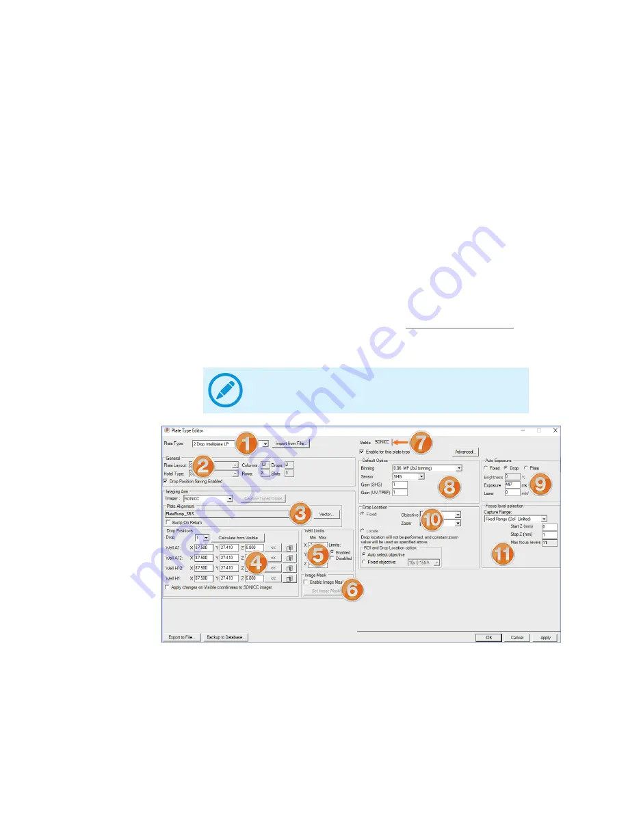
Adjust the settings you want to change using the table below as a guide. If you need further
assistance, contact FORMULATRIX support.

The Plate Type Editor

Содержание ROCK IMAGER FRAP Benchtop

Страница 1: ...Original Instructions Applies to RI 1000 RI 182 RI 54 RI 2 FRAP Benchtop SONICC Benchtop User s Guide ROCK IMAGER ...

Страница 2: ...User s Guide Sixth Edition Revised January 2019 RIG V37R019 ROCK IMAGER ...

Страница 3: ...latrix com To comment on FORMULATRIX documentation email publications formulatrix com FORMULATRIX European Representative Carl Pedersen Support Europe Phone 44 7805512001 carl formulatrix com Acknowledgements SONICC was invented by Garth Simpson s group at Purdue University and is exclusively licensed by FORMULATRIX FRAP was developed in collaboration with Vadim Cherezov TSRI and the JCIMPT center...

Страница 4: ...delines 4 Mechanical Hazards 4 Electrical Hazards 4 Laser Hazards 5 Safety Labels 5 Specifications 6 Dimensions 6 Computer Requirements 7 Environmental Requirements 7 Electrical Requirements 9 Recommended Electrical Configurations 10 Overview 11 Key Features 11 Capabilities 11 RI 1000 12 RI 182 and RI 54 13 RI 2 13 Table of Contents ...

Страница 5: ...First Use 39 First Use 40 Using RI 1000 RI 182 RI 54 41 Adding Plates 41 Initiating an Imaging Session 42 Searching for Plates in Storage 43 Viewing a Plate s Automatic Imaging Schedule 44 Removing Plates 45 Stop the Ejection of Expired Plates 45 Using RI 2 FRAP Benchtop SONICC Benchtop 46 Instant Imaging 46 Imaging a Plate with FRAP Benchtop 47 Imaging a Plate with SONICC Benchtop 49 Imaging a Pl...

Страница 6: ...op Location 67 Using the Plate Type Editor 68 Improving Images 79 Setting Up Plate Definitions 79 Applying Plate Masks 81 Tuning Plates in ROCK IMAGER 83 Clearing Drop Locations 87 ROCK MAKER The Crystallography Center 88 Creating an Experiment in ROCK MAKER 88 Printing a Barcode Label for a Plate 89 Viewing and Scoring Images in ROCK MAKER 90 FAQs 93 UV FAQs 96 SONICC FAQs 98 FRAP FAQs 101 Mainte...

Страница 7: ...mply with the procedures outlined in the ROCK IMAGER User s Guide or use of the products in violation of applicable laws rules or regulations Except as otherwise expressly provided in this user guide any alteration adjustment or modification to the products will void the product warranty Read understand and observe all safety information and instructions in this manual before using ROCK IMAGER Ple...

Страница 8: ...is icon denotes a fire hazard and advises you of precautions to take This icon denotes a note and alerts you to important information This icon denotes a laser hazard This icon denotes a warning bold Bold text denotes items you must select or click in the software such as menu items and dialog box options Bold text also denotes parameter names Monospace Text in this font denotes text or characters...

Страница 9: ... is also CDRH Chapter 21 CFR 1040 10 compliant Safety Information Chapter 2 Regulatory Compliance This device contains a laser radiation device within the barcode scanner Do not stare into the beam or bodily injury may occur The door should only be opened under the direction of trained FORMULATRIX personnel applies to RI 1000 RI 182 RI 54 SONICC Benchtop and FRAP High voltage components in the ele...

Страница 10: ...abels Turn OFF power before inserting or removing power cables Do not open the door to the ROCK IMAGER chassis without express instruction from trained FORMULATRIX personnel applies to RI 1000 182 54 and SONICC Benchtop only ROCK IMAGER is a complex electromechanical device Only persons with the proper training should service or operate the product Avoid damage to the power cables Do not apply unn...

Страница 11: ...C Benchtop or ROCK IMAGER 1000 Dual Imager with SONICC while the laser is in use under ANY circumstances Laser Hazards Safety Labels Do not remove or alter any safety labels or warnings from FORMULATRIX products This device contains a laser radiation device within the barcode scanner Do not stare into the beam or bodily injury may occur The FRAP imager has one safety label affixed to the cover of ...

Страница 12: ...834 x 2197 x 1230 mm 33 x 87 x 49 462 kg 1019 lbs RI 182 865 x 1028 x 798 mm 35 x 41 x 31 161 kg 355 lbs RI 54 755 x 1016 x 641 mm 30 x 41 x 26 114 kg 252 lbs RI 2 419 x 580 x 354 mm 16 5 x 22 8 x 13 9 23 kg 51 lbs SONICC Benchtop 642 x 980 x 700 mm 25 x 39 x 28 68kg 150 lbs FRAP Benchtop 651 x 877 x 697 mm 26 x 35 x 27 45 kg 100 lbs Specifications Chapter 3 Dimensions ...

Страница 13: ...GER 1000 SQL Server Express Standard Edition version 2008 R2 Minimum or 2014 Recommended Dedicated database server Recommended Network connection Remote access e g WebEx TeamViewer VPN Recommended Email Server access SMTP server credentials Optional UPS unit Windows 7 32 bit or 64 bit Windows 10 64 bit 4 GB RAM 2 GB available Hard Disk space Dual core 1 GHz 1024 x 768 pixels screen resolution 3 5 ...

Страница 14: ...rver access SMTP server credentials Network connection for email access Recommended Windows 7 32 bit or 64 bit Windows 10 64 bit 4 GB RAM 1 GB available Hard Disk space Dual core 1 GHz 1024 x 768 pixels screen resolution 3 5 and 4 5 NET Framework SONICC and FRAP Benchtop SQL Server Express Standard Edition version 2008 R2 Minimum or 2014 Recommended Remote access e g WebEx TeamViewer VPN Recommend...

Страница 15: ...ecommended UPS 5000 W ROCK IMAGER 1000 Dual Imager w Frap Peltier Cooled Cooling Unit 100 240 V 50 60 Hz 1000 W max 1 ph Robotics 100 240 V 50 60 Hz 240 W max 1 ph Computer 525 W max 1 ph Recommended UPS 3500 W 1000 Dual Imager w SONICC Peltier Cooled Cooling Unit 100 240 V 50 60 Hz 1000 W max 1 ph Robotics 100 240 V 50 60 Hz 835 W max 1 ph Computer 525 W max 1 ph Recommended UPS 4500 W ROCK IMAGE...

Страница 16: ...ax 1 ph Computer 525 W max 1 ph SONICC Benchtop Imager 100 240 V 50 60 Hz 1195 W max 1 ph Computer 525 W max 1 ph Recommended UPS 3340 W FRAP Benchtop Imager 100 240 V 50 60 Hz 600 W max 1 ph Computer 525 W max 1 ph Recommended UPS 2250 W RI 182 RI 54 RI 2 RI 1000 Recommended Electrical Configurations ...

Страница 17: ... optional and SONICC optional imaging capabilities Custom image scheduling Nightly diagnostic reports sent to FORMULATRIX for continued quality control ROCK IMAGERs are designed to minimize vibration to microtiter plates to prevent environmental disturbance Temperature control with sensors at a variety of locations that monitor temperature to 0 1 C Easy to use control software that runs smoothly o...

Страница 18: ... Lipidic Cubic Phase LCP Compatible All systems can support LCP or membrane crystallization imaging with standard microtiter plate heights The RI 1000 can support up to 1500 individual thin glass LCP plates with an optional storage rack modification Performance Sitting drop imaging as fast as 0 8 seconds per drop with one slice fixed focus and fixed exposure The flagship model in the ROCK IMAGER l...

Страница 19: ...ds available RI 54 Can hold up to 54 SBS plates or up to 28 Linbro plates Capable of Peltier cooling to 5 C below or 7 C above ambient Performs automatic scheduled imaging Vibration isolated storage Visible and UV imaging methods available ROCK IMAGER 2 is the smallest of the ROCK IMAGERs useful for those of you who aren t interested in storage capabilities or who have space concerns but are still...

Страница 20: ...our computer screen becomes the microscope s eyepiece and physical optics and imager controls are replaced by on screen controls All ROCK IMAGERs integrate with ROCK MAKER FORMULATRIX s crystallization experiment lifecycle management software Automated imaging is scheduled and managed through ROCK MAKER User Interfaces ROCK IMAGER Software ROCK MAKER Software ...

Страница 21: ...etects the second harmonic signal generated by chiral crystals such as proteins and is capable of detecting micro crystals 1 µm in opaque solutions It is available as a separate imaging system in a RI 1000 chassis or as a standalone benchtop imaging system FACIT FORMULATRIX Advanced Contrast Imaging Technology FACIT allows you to control the illumination pattern on a drop in order to see more crys...

Страница 22: ...00 with SONICC Plate Load Port Temperature Control Imager SONICC Imager Electronics Drawer Temperature Control ROCK IMAGER 1000 monitors and regulates temperatures to within 0 1 C with the assistance of its air circulation system The base model features a Peltier heat exchanger that regulates temperatures to 5 C below ambient to 7 C above ambient with 0 5 C precision Peltier enhanced panels can be...

Страница 23: ...robot s moving parts Plate Storage Hotels ROCK IMAGER can image and store up to 1000 microtiter plates This can be reduced to 250 or 500 for cost or use case needs For LCP projects the ROCK MAKER 1000 hardware can be altered to fit up to 1500 glass sandwich plates Fault Tolerance with Crash Sensors Crash sensors detect when a robot arm collides with something during regular operation In the event ...

Страница 24: ...wer Switch SBS and Linbro Hotels in Load Port Load Port Door Power Switch The power switch is covered by a small door in the upper left corner of the front of the imager You should leave the imager powered on during idle times to allow for automatic scheduled imaging and to maintain a constant temperature for any plates stored in the system s hotels SBS and Linbro Hotels in Load Port The storage h...

Страница 25: ...orized zoom optics with 1 µm feature resolution provides sharp high contrast images to the camera and allows small feature zooming UV Camera Optional UV Imaging used to identify protein crystals based on the florescence of tryptophan under UV light is an optional addition to ROCK IMAGER 2 The UV imager uses 100 UV optimized components including UV grade optics a UV sensitive camera and UV lighting...

Страница 26: ...e barcode scanner allows for automated imaging and passes the images over to ROCK MAKER to be stored in a user friendly viewing environment Power Switch A switch that turns the FRAP on and off FRAP benchtop was not designed to be an incubator so if not in use FRAP should be powered off Main Door The door to FRAP is secured with a hex key locking mechanism You must open the door to place a plate in...

Страница 27: ...RAP optics i e bleaching laser fluorescence light source and CCD camera has a footprint of only 15 cm x 27 cm Compound Zoom Turret Multiple objectives are available for use providing a large field of view with an option to zoom into areas of interest FRAP comes standard with two objectives 1 1x and 5 5x The lower magnification objective is used for drop location and the higher magnification object...

Страница 28: ...d one for the imaging optics The power switches should be left on at all times unless you want to power off the imager during periods of inactivity When you power off the imager you must first exit the software and then push each power switch to the OFF position Main Door The main door is latched securely with a hex key and should not be opened at any time Load Port Door Plates can be safely added...

Страница 29: ...Laser Pulse Generator A fiber based femtosecond laser pulse generator provides a robust laser power source Laser controls are fully integrated with the ROCK IMAGER software removing the need for manual adjustments Door Sensor The laser will shut off if the door sensor detects that the door is open This is implemented as a safety feature You should not open the door at any time Continuously opening...

Страница 30: ...as the light detector in SONICC Photons of light generated from the sample are funneled to the PMT creating a cascading electric response that multiplies the signal as many as 100 million times The PMT response is then mapped to a pixel in an image based on the time that it was acquired to create the SONICC image The PMT has been upgraded in SONICC instruments manufactured since January 2018 to ha...

Страница 31: ...ort handle from the load port hotel L Hex Wrench Key The L Hex Wrench key is a special tool used for locking and unlocking the door to the chassis of ROCK IMAGER except ROCK IMAGER 2 which has no enclosure SBS and Linbro Load Port Hotels Additional load port hotels are available for both SBS RI 1000 182 and 54 and or Linbro plates RI 182 only SBS Load Port Hotel Part No 200062 Linbro Load Port Hot...

Страница 32: ...Adaptor Part No LCPPA Linbro Plate Adaptor for RI 2 Systems Part No 200547 EasyXtal Plate Adaptor for RI 2 Systems Part No 200544 Barcode Printer Supplies 4000 Custom Labels for Barcode Printer Part No 201621 LCP Plate Adaptor RI 2 Plate Adaptor Barcode Labels ...

Страница 33: ... per second with fixed or compound zoom objectives Camera and optics settings can be manipulated through the Plate Type Editor the manual imaging controls or via Imaging Setting settings which are defined in ROCK MAKER Imaging Setting settings will override any settings configured on the ROCK IMAGER side so if you re trying to improve your images your best bet is to find settings you like in manua...

Страница 34: ...ight from a cone to a column and vice versa for automated contrast adjustment A cone of light will produce images with the least shadowing while a column of light produces images with the highest contrast Motorized Polarizer To help identify crystals ROCK IMAGER has a motorized rotating polarizer and a fixed polarizer The polarizers are 95 efficient and transmit light of 30 at 400 700 nm Köhler Il...

Страница 35: ... switching between UV and visible light optical paths Fully integrates with ROCK MAKER crystallization software and other Laboratory Information Management System LIMS crystallization software Compound Zoom Option Includes a 2 5x 5 0x and 7 0x objectives on a motorized turret Fixed Zoom Option Choice of a 2 5x 5 0x or 7 0x objective The Second Order Non linear Imaging of Chiral Crystals SONICC ima...

Страница 36: ...G Also all aggregated and solubilized protein will generate no SHG yielding extremely high contrast images How Does SONICC Work SONICC is a microscope that uses a laser beam to scan over the sample and then collects the signal generated to create an image 1 A femtosecond fiber laser is used to generate the 1064 nm incident IR light 2 The beam is raster scanned with a resonant mirror 8 kHz along th...

Страница 37: ... discrimination between protein and salt crystals This imaging mode takes advantage of the intrinsic aromatic amino acid residues ex Tryptophan in the proteins When excited with UV radiation the tryptophan in the proteins fluoresce making it very easy to determine whether or not a crystal is proteinaceous In order to probe this fluorescence the laser is doubled with a NLO nonlinear optical crystal...

Страница 38: ... a single component or double component 2 D diffusion equation FACIT FORMULATRIX Advanced Contrast Imaging Technology is a hardware option developed at FORMULATRIX in which a digital light projector modifies the light pattern used to illuminate your drops Any pattern you can imagine can be projected onto a drop Common patterns from a variety of different angles including darkfield and glancing ill...

Страница 39: ...proteins in solution with a simple one step protocol can generate high contrast fluorescence images of all proteins including those without tryptophan Key Features Find hidden protein crystals and distinguish them from salt even protein with little to no tryptophan Differentiate between crystals of a protein protein complex and crystals of just a single protein Faster imaging time 96 well plates c...

Страница 40: ...different filter modules capable of imaging your crystal with different excitation and emission wavelengths The standard package includes one 290 nm excitation module for UV imaging and two visible fluorescence filter sets for detecting the fluorescence from Texas Red and Fluorescein dyes If you would like to image fluorescence from other dyes and install a different filter module contact support ...

Страница 41: ...amenable for your specific protein sample A simple one step labeling protocol is suggested below To label a protein sample using a simple 0 1 protein labeling protocol2 1 Prepare a 5 mM stock solution of a succinimidyl ester dye in DMSO 2 Add appropriate amount of dye to protein solution for 0 1 labeling of lysine residues assuming a 1 1 stoichiometric labeling efficiency to amine residues 3 Wait ...

Страница 42: ... image an entire plate with the MFI imaging settings in the Imager menu point to Image click Plate or click Plate Using to define a custom imaging setting To manually explore the contents of your plate conduct a Manual Imaging session see Manually Inspecting a Plate on page 60 To image the current drop with the MFI imaging settings in the Imager menu point to Image click Drop or click Drop Using t...

Страница 43: ...oint to Image and click Drop Using If you have tagged certain drops as interesting in ROCK MAKER you can opt to image only those drops by going to the Imager menu and selecting Interesting Drop s in the Image menu to use the default imaging setting OR Point to Image and click Interesting Drop s Using to use a custom imaging setting 4 When your plates have been imaged at least once you can view the...

Страница 44: ...nsmits UV light through the sample and then detects the same wavelength UV light on the camera Areas that absorb the UV light create contrast enabling you to see differentiating features in your crystallization drops UV absorption can be helpful for imaging drops that are not UV fluorescence for example DNA RNA and proteins without tryptophan UV Absorption Imaging Salt Crystals RNA ...

Страница 45: ...provider Make sure the ShockWatch sticker is not red if tripped the center turns red as shown in the image at right below FORMULATRIX support will have sent you an email with crate dimensions Please ensure that you have ample space in a dry area away from extreme temperatures to store ROCK IMAGER until support arrives to begin installation Make sure that the This Side Up sticker always points upwa...

Страница 46: ...e of the machine in the upper left corner 3 Start the ROCK IMAGER software by double clicking the ROCK IMAGER icon on your computer s desktop 4 ROCK IMAGER will home the PSR Plate Storage Retrieval arm then the Imager hand and then the Load Port if you have one 5 Once ROCK IMAGER is ready you can begin imaging plates Refer to the next two sections for more information 6 When ROCK IMAGER will not b...

Страница 47: ...ving plates to storage is recommended if you are using ROCK IMAGER 1000 because of greater temperature control When you move a plate to storage ROCK IMAGER takes the plate and puts it in a storage hotel away from the load port The imager will then image the plate according to its automatic imaging schedule Adding Plates ROCK IMAGERs 1000 182 and 54 have the ability to image experiment plates in ei...

Страница 48: ...ng Protein Sample on page 35 Imaging 1 Using the Search sub tab of the Plates tab locate the plate in the imager 2 Once you locate your plate you have several options Click on the plate to highlight it and select from the options below If you want to image more than one plate press and hold the Ctrl key on your keyboard while selecting plates To image an entire plate with the default imaging setti...

Страница 49: ...le filters its contents with each keystroke you make 3 Once the plate of interest appears in the table right click on the name of the plate to view the options for the plate You can See the plate s automatic imaging schedule and other information by selecting Plate Information Image the plate with its regular imaging setting by selecting Image Plate Image the plate with a custom imaging setting by...

Страница 50: ...Prerequisites The plate is inside the imager You know the plate s project name experiment name plate number dispense date user name owner plate type plate ID barcode location and or state To view a plate s imaging schedule 1 Use the Plates tab to locate your plate inside the imager 2 Right click on the plate and select Plate Information A new window opens that contains two tabs Schedule and Inform...

Страница 51: ...initiate imaging until they are in the load port If the load port is full the plates will wait in storage and they will automatically be moved to the load port as slots become available To cancel movement to load port right click on the greyed out plate and click Cancel Move to Load Port 2 Open the load port door If you are using ROCK IMAGER 1000 the load port shuttle will move towards you Remove ...

Страница 52: ...are in manual mode because there is no storage However if you want to image the same plate multiple times you can switch to Automatic Mode When you create an Instant Imaging session ROCK MAKER creates a special folder for your experiment and images called Instant Imaging After the imaging process you can use ROCK MAKER to move the experiment file to a more appropriate location in the Explorer tree...

Страница 53: ...an uncheck certain wells if you don t want to image them 9 Select Instant Imaging options for a plate at slot 2 Skip this step if you are only using slot 1 10 Click OK to complete Instant Imaging setup for the plate at slot 1 2 Prerequisites You have created an experiment in ROCK MAKER If you are attempting to image a plate without a barcode please see Instant Imaging on the page 46 Your plate has...

Страница 54: ...gs go to the Imager menu point to Image and select Drop Using If you have tagged certain drops as interesting in ROCK MAKER and wish to image only those drops go to the Imager menu point to Image and select Interesting Drops to use the default imaging setting or point to Image and select Interesting Drops Using to use a custom imaging setting1 If you want to run Full Recovery FRAP imaging on the d...

Страница 55: ... in the Imager menu click Scan Plate s 5 Choose from the following options To image an entire plate with the default imaging setting in the Imager menu point to Image and click Plate s or go the Scheduling tab right click on a plate and select Image Plate To image an entire plate with the imaging setting s of choice in the Imager menu point to Image and click Plate s Using ROCK IMAGER will display...

Страница 56: ... only See Labeling Protein Sample on page 35 Imaging a Plate with RI 2 1 Place the plate in any available slot with the label facing towards you 2 Tell ROCK IMAGER to scan the barcode Using the ROCK IMAGER software go to the Imager menu and select Scan Plate s Notification Informing Users of Plate Type Mismatch Imaging a Plate with RI 2 Note If the SONICC laser is defective during imaging sessions...

Страница 57: ...want to use and select which slot s you want to image Then click OK to run the imaging To inspect your plates well by well or drop by drop without taking images go to the the Live Image tab and use the manual navigation controls To image a specific drop with the default imaging settings in the Imager menu point to Image and select Drop Selecting Imaging Settings and Slots in the Image Plate Using ...

Страница 58: ... window Click OK to run the imaging 4 When your plates have been imaged at least once you can view the images in ROCK MAKER As long as ROCK IMAGER Processor is running you should see thumbnails of your images on the Canvas If your images are not showing up try pressing F5 on your keyboard while in ROCK MAKER to refresh the image display A plate s automatic imaging schedule and information can be s...

Страница 59: ... positioning on the same drop within 10 microns The software algorithm repositions the end state image to correctly overlay with the pre bleach image Expected values are approximately 10 30 µm Image offsets between the pre bleach and post bleach images are also calculated However very minimal changes are expected here as the stage does not reposition in between the acquisition of these images Star...

Страница 60: ...interest are protein crystals Tops of plates and sealing tape may generate significant amounts of SHG and fluorescence If the laser is focused on these regions then one may expect strong background interference from these materials However the depth of focus of the beam is small enough that when the laser is focused in the drop there should be no out of plane contributions from the plates and tape...

Страница 61: ...rtant to compare to the SHG channel to determine if it is crystalline The use of the UV TPEF channel provides a clear assessment of each drop which can be seen in the figure on the next page In both rows a and b contrast is observed in both the UV TPEF and SHG channel indicating protein crystals The well imaged in row c results in fluorescence but no SHG indicating precipitated aggregated protein ...

Страница 62: ...ttings SONICC Benchtop Reference Plate Image Analysis As SONICC Benchtop lacks plate storage image analysis is performed by support engineers at initial installation beginning January 2016 to set the benchmark data point and at all subsequent support visits However bi weekly tests should be performed manually by the lab manager or other designated personnel to properly monitor the integrity of the...

Страница 63: ...ring FRAP imaging Bleach Options The Bleach Options area provides two major settings Pulse Laser for and Drop area to include in Random Bleach Position Pulse Laser for This field allows you to specify the amount of time the laser is focused on the drop to bleach the fluorophores Drop area to include in Random Bleach Position A bleach position is randomly chosen in the specified area One or two dif...

Страница 64: ...ttings Imaging Settings An imaging setting is a collection of settings that tells ROCK IMAGER how an experiment plate should be imaged Imaging settings are configured in ROCK MAKER The name of the specific imaging setting that has been set in ROCK MAKER for a Single Drop Full Recovery imaging session appears in the Single Drop Full Recovery box If you change options here you are changing the defau...

Страница 65: ... single diffusion rate This method is accurate enough for most applications if protein molecules are labeled with dye Double Component Fitting Fits the pixel intensity recovery data with two Bessel functions The result of this numerical fit is two distinct diffusion rates This method is useful if the protein is not purified well Some small molecule lipids are labeled with dye which generate the tw...

Страница 66: ...oaded the plate to ROCK IMAGER scanned the barcode and moved the plate to the desired imager e g Visible UV Fluorescence FRAP SONICC You have labeled your protein Multi Fluorescence Imaging only See Labeling Protein Sample on page 35 To manually inspect a plate 1 Before you can use any of the manual imaging controls you have to put ROCK IMAGER into Manual Mode To do so go to the Scheduling menu an...

Страница 67: ...you will need to manually go to the Scheduling menu and select Automatic Mode to resume Automatic imaging 3 If you are not already on the Live Image tab go to the Imager tab and click the Live Image sub tab 4 Under Camera Control set Live Image to by clicking the Live Image button 5 Use the Well Controls to explore the contents of your plate 6 Use the Optics Controls and Camera Controls to fine tu...

Страница 68: ...h between available imaging methods You might find it useful to locate a drop using Visible light and then imaging it with UV FRAP or SONICC for example The Imager Control panel when displayed is found on the Live Image sub tab of the Imager tab at the top of the right hand side of your screen Imager Control Panel Manual Imaging Controls Important Leaving Live Image on for an extended period of ti...

Страница 69: ... the screen Adjusting these controls does not affect the way your images are captured during automatic scheduled imaging sessions as those parameters are defined by the imaging setting s selected in ROCK MAKER The Camera Control panel is found on the Live Image sub tab of the Imager tab The contents of the Camera Control panel vary depending on the imaging method you are using There are three poss...

Страница 70: ...s Controls Camera Controls General Camera Control UV Camera Control Panel SONICC Camera Control Visible Light Optics Controls UV Optics Controls FRAP Optics Controls SONICC Optics Controls SLP Visible Light Optics Fluorescence Optics Controls SLP UV Optics Controls ...

Страница 71: ...can either adjust leveling for images on an individual basis or adjust leveling for one image right click and select Save Current Threshold for Auto Leveling Once you set the initial auto leveling values ROCK IMAGER attempts to emulate the resulting brightness and contrast for every image in that inspection when you click the Auto button To adjust limits Click and drag the triangles on the Levelin...

Страница 72: ...Focus with Limits The first four fields Max focus levels above Focus threshold above Max focus level below Focus threshold below determine the stack of images to be taken around what ROCK IMAGER determines to be the best focus point These settings are configured on a per plate basis by our technicians when ROCK IMAGER is installed but you can adjust them Auto Focus with Limits factory settings for...

Страница 73: ... then uses normal imaging settings to photograph the drop The Drop Location algorithm can be executed from the Camera Control panel during a manual plate inspection It s also executed on a per plate or per drop basis for every imaging session or only the first time a plate is imaged during automatic imaging sessions Automatic imaging drop location settings are controlled from the Plate Type Editor...

Страница 74: ...t We only recommend advanced users to modify these settings The information below is for lab managers so that they may adjust settings as they see fit Note The screenshot shown below is from a ROCK IMAGER Dual Imager system with SONICC The options on your screen may vary slightly To Use the Plate Type Editor 1 After you open ROCK IMAGER click File and select Plate Type Editor 2 Adjust the settings...

Страница 75: ...e this plate type is imaged or if ROCK IMAGER will save the settings to memory Imaging time is faster when Drop Position Saving Enabled is selected The Imaging Arm area enables you to choose which imager type you want to use If you purchased a dual imager system you will have two Imager options such as Visible and SONICC or Visible and FRAP You can select the desired imager that you would like to ...

Страница 76: ...ture in ROCK IMAGER requires ROCK MAKER 2 7 or newer Certain plate types fluoresce causing false positives You can mask a plate to increase Auto Score accuracy which will hide the edges of a plate and instruct Rock Image Processor to ignore fluorescence from those areas when computing a positive or negative score for the drop The number and type of imagers available here depends on the imaging typ...

Страница 77: ...maging Using two different drop zooms can be useful for imaging plates that have two different drop sizes Drop 1 Type the desired zoom value for Drop 1 in the Drop 1 box Drop 2 Type the desired zoom value for Drop 2 in the Drop 2 box Override Exposure Override default Select to enable a fixed exposure for all imaging modes Objective 1 5 Type a value to determine the exposure when you are using 1 5...

Страница 78: ... would like ROCK IMAGER to use custom drop zooms defined in the Drop 1 and Drop 2 boxes during plate imaging Using two different drop zooms can be useful for imaging plates that have two different drop sizes Drop 1 Type the desired zoom value for Drop 1 in the Drop 1 box Drop 2 Type the desired zoom value for Drop 1 in the Drop 2 box Override Exposure Override default Select to enable a fixed expo...

Страница 79: ...x Objective Select the desired objective for Drop 1 from the Objective list ROCK IMAGER will use both zoom and objective settings when locating a drop ROI and Drop Location option Auto select objective When selected ROCK IMAGER automatically uses the best objective setting for finding a drop location on drop 1 Fixed objective When selected you can select a fixed objective for ROCK IMAGER to find a...

Страница 80: ...sponding box The Default Optics field contains the settings for the optics components and resolutions used during drop imaging including Gamma Condenser Gain and Polarizer If you are using FRAP you will see the Fluoro Light option which enables you to change the fluorescence signal intensity If you are using ROCK IMAGER with FORMULATRIX Advanced Contrast Imaging Technology FACIT you can control th...

Страница 81: ...p left corner and the rest of the background appears dark Top right When selected ROCK IMAGER illuminates the specimen from the top right corner The specimen appears bright at the top right corner and the rest of the background appears dark Bottom right When selected ROCK IMAGER illuminates the specimen from the bottom right corner The specimen appears bright at the bottom right corner and the res...

Страница 82: ...Pixel Min White Pixel Max Open Iterations and Max Aspect Ratio Min Length µm Controls the minimum number of µm in a blob for that blob to count as a drop Max Length µm Controls the maximum number of µm in a blob for that blob to count as a drop White Pixel Min The minimum range of pixel intensities maps to white when converting a sobel image to a binary image White Pixel Max The maximum range of p...

Страница 83: ...nes the amount of optical brightness The higher the Exposure value the brighter the image will be Gain Determines the amount of digital brightness The higher the Gain value the brighter the image will be Condenser Determines the image s contrast The higher the Condenser value the sharper the contrast will be Brightness Determine the brightness of the light source The higher the Brightness value th...

Страница 84: ... axis between the start and stop heights and also determines the best number of slices to take based on the Depth of Field of the optics in use The three settings below the Focus level selection determine how the slices are captured The Start Z and Stop Z values determine the range along the Z axis where ROCK IMAGER captures slices of the drop The Max focus levels settings equates to how many slic...

Страница 85: ...te definitions depending on the plate types you use When setting up a plate definition you will need to configure some important settings such as X Y Z coordinates for the four corner well locations i e top left top right bottom right and bottom left You can always contact support formulatrix com for help in setting up plate definitions Prerequisites You have added a container plate type in ROCK M...

Страница 86: ...er menu select Crosshairs c On the main ROCK IMAGER software window go to the Well Control panel and select one of the speed options Fast Medium or Slow d Use the arrow buttons on the Well Control panel to move the imager to the first well location such as Well A1 and adjust its positions Move the crosshairs to the center of the well and use the Z axis control arrow buttons located to the right to...

Страница 87: ...should be used for drops that are centered in the well with consistent relative positions This method will have the fastest imaging time and is recommended for routine sitting drop experiments Standard Drop Location should be used for soluble protein experiments and is useful for plates where the drop position is not consistent and the size of the drops are small relative to the well area 7 When d...

Страница 88: ...ck the Enable Image Mask checkbox Enable Image Mask 3 Click Set Image Mask The Plate Image Mask window opens 4 Select a shape for your plate mask from the Shape list Options include circle ellipse square rectangle and rounded square rectangle Set Image Mask Tip If the image of your drop is not clear enough click Cancel and adjust the view of your drop on the Live Image tab using the manual imaging...

Страница 89: ... of the four corner wells using the ROCK IMAGER Plate Type Editor Prerequisites You are comfortable with the Plate Type Editor You have the plate that you want to tune You have created an experiment for the plate in ROCK MAKER To tune drop locations 1 Go to the File menu and select Plate Type Editor to open the Plate Type Editor 2 Select your Plate Type from the plate type list Even a new plate wi...

Страница 90: ...enter point of the drop so that you can easily determine the exact drop coordinates When tuning the drop position you can also use the Calculate from Visible button to generate the coordinates for SONICC or FRAP calculated from the coordinates used for Visible imager with the necessary offset applied This gives you a good starting point from which to further tune the drop locations for the best po...

Страница 91: ... been added to ROCK MAKER 6 Then click the Capture Tune Drops button A message will appear when the capturing process is finished 7 Then click Apply and click OK 8 Move the plate to the SONICC or FRAP imager and on the Imager Control panel change the imager to SONICC or FRAP 9 Open the Plate Type Editor and click the Calculate from Visible button to generate the drop coordinates that will be displ...

Страница 92: ...verlay the current live image with the captured drop image for Well A1 14 In the live imaging mode use the interpolated image to check whether the drop position is centered based on the center point shown in the captured image which has been tuned in Visible mode 15 Use the green arrows on the Well Control panel to control the plate movement to adjust the drop location You can use Medium or Slow m...

Страница 93: ...on your plate You want to remove or reset one or all drop locations To clear drop locations on a per plate basis 1 Locate the plate using any one of the Plates sub tabs for further assistance see Searching for Plates on page 43 2 Right click on the name of your plate and select Clear Drop Location Positions A confirmation message appears To clear drop locations on a per drop basis 1 Locate the pla...

Страница 94: ...ill need to create a protein formulation define the volumes and locations on your plate and add a screen ROCK MAKER includes walk through tutorials that assist you with these processes via a feature called ROCK MAKER University RMU RMU includes both tours and tutorials a tour is indicated by a tour bus tutorials are indicated by graduation caps Tours are informative Tutorials assist you with compl...

Страница 95: ...nstructions Once you have designed and edited your experiment you must print a barcode label for the plate Prerequisites You are running ROCK MAKER version 3 0 or newer To print a barcode label 1 In the ROCK MAKER main window locate the experiment you created in the Explorer 2 Click the small black triangle next to your experiment to display the experiment plate The experiment plate is indicated b...

Страница 96: ...CK IMAGER To view Images in ROCK MAKER 1 In the Experiment contextual tab set click the View tab and click the Image View button in the Canvas Mode group 2 Click the Image View button on the View bar 3 Click the Navigator button on the View bar to be able to look at image thumbnails and move around from one image to the next The Navigator contains all controls necessary to browse through plates we...

Страница 97: ...o to the Drop tab and use the F11 and F12 keys on your keyboard To compare an image with another image press and hold the Ctrl key on your keyboard and click on the images you want to compare To change the way you are navigating through images use the Navigate by list Using the Navigator Comparing Images The Navigate by List ...

Страница 98: ...d green lines in between the histogram to the left most part of your image s histogram and the right most part for the best contrast and brightness To score images 1 While in Images view select a drop by clicking it If you want to assign the same score to multiple drops select them all from the Canvas tab 2 Press a number on your keyboard to assign a score ROCK MAKER moves you to the next image OR...

Страница 99: ...mage right away How do I do it 1 Insert your plate in the load port 2 Scan the barcode by going to the Load Port menu and selecting Scan Load Port 3 Move the plate to the imager by going to the Imager menu pointing to Image and clicking Plate to image the plate with the default imaging setting or pointing to Image and clicking Plate Using to image the plate with a new imaging setting How do I imag...

Страница 100: ... select Immediate or Daily Digest from the Notification Type list The drop locations ROCK IMAGER found on my plate aren t accurate How do I improve them If you are using automatic drop location see Clearing Drop Locations on page 87 for information on how to clear the current drop locations If you are using fixed drop location 1 On the File menu click Plate Type Editor 2 Select your plate type fro...

Страница 101: ...ctions If your images still aren t showing up contact support by emailing support formulatrix com How do I save the image I m seeing on the Live Image tab Ctrl S isn t working In ROCK IMAGER Ctrl S tells the imager to store the contents of the load port To save the image you re viewing go to the File menu and select Save Image ROCK IMAGER can t find my plates in the load port What do I do First ch...

Страница 102: ...nder UV Technically any tryptophan will fluoresce at any concentration As far as what concentration threshold is needed in order for the florescence to translate to the image captures the answer varies with exposure time ambient light gain setting plate media interference etc Can we adjust the brightness of the UV LED No The LED is at it s max without burning out as it is Too much LED will cook yo...

Страница 103: ...o the camera media absorption or solution absorption again All three of these scenarios are unlikely given carefully chosen media and reasonable drop sizes Where do you place the UV lens Does it image from the top of the plate or from the bottom If from the top then we will have to put the glass sandwich plates upside down Does it affect the imager operation The UV lens is above the plate Putting ...

Страница 104: ...susceptible to SHG and will generate low amounts of signal Will salts produce signal They can if they are chiral but the majority of salts are achrial and therefore do not generate SHG How is SONICC different than fluorescent imaging Fluorescent imaging takes advantage of either the endogenous fluorescence of the protein or the use of fluorescent tags Although the fluorescence is bright and easily...

Страница 105: ...lity based on polarization changes of the emitted light Specifications How small of a crystal can SONICC detect Theoretically the lower limit of detection can be estimated by the forward to backward ratio of the SHG Based on the coherence length of the generated SHG and the refractive index of the material this lower limit ranges from 90 nm 300 nm in thickness In practice crystals of the size of 1...

Страница 106: ... detection expedites the process of monitoring APIs and can also give insights crystallization kinetics What percent crystallinity can SONICC detect The theoretical detection limit estimated by the coherence length of SHG and refractive index of griseofulvin is 90 nm in thickness corresponding to 3 4 x 10 9 crystallinity An upper limit of detection would be 5 µm corresponding to crystallinity of 6...

Страница 107: ...1000 The ROCK IMAGER 1000 with FRAP maintains two independent imaging stations You are able to run a FRAP experiment in parallel with bright field color imaging Do I need to run FRAP drop by drop You can opt to run FRAP in a single LCP drop However the system is built with hands free operation in mind You only need to set up the FRAP inspection schedule the system will automatically load the plate...

Страница 108: ... or phone with any questions We are always happy to hear from our customers and provide assistance Direct the ROCK IMAGER drain tube to a drain container to hold the water from the cooling units RI 1000 only Check the drain container periodically and make sure to empty it when the water is full What is included in software maintenance Software maintenance includes all product upgrades excluding in...

Страница 109: ...omer to diagnose any computer errors and re install the software but the customer must work with the computer manufacturer directly to resolve any hardware issues What is priority shipping and travel You can choose to pay for travel and priority shipping in advance for up to one year Please ask your sales or support person for a quotation What happens if I am out of maintenance and I have a proble...

Страница 110: ...Mode list provides you with two UV imaging options including Absorption and Fluorescence UV absorption imaging is available to new ROCK IMAGER 1000 models only Objective SLP Visible UV Fluorescence FRAP SONICC To change the Objective values click the corresponding list and then select the desired value as necessary Zoom Visible SLP Visible UV The Zoom field is generated by the current zoom setting...

Страница 111: ...ll match the FOV for visible images which also enhances the viewing of images in ROCK MAKER Field of View FOV Visible SLP Visible UV Fluorescence FRAP SONICC You can use the FOV fields to manually set the size in µm of the image you would like to view As you change the FOV value using either the text entry field or the arrows the zoom value automatically adjusts Sensor SONICC The Sensor selection ...

Страница 112: ...trated in a column of light as opposed to a cone Adjusting the condenser value can improve image contrast Increasing the condenser angle increases the contrast Polarizer Visible SLP Visible This field describes the angle at which the polarizer lens is projecting the light from 0 360 Recommended settings are 0 or 90 At 0 you are not using cross polarized imaging At 90 you are using cross polarized ...

Страница 113: ... amount of time in milliseconds that the camera s shutter remains open when capturing an image which determines the amount of light allowed to fall on the camera s sensor affecting the image s brightness Click Auto to run the auto exposure algorithm see About Auto Focus on page 66 for more information Binning and Image Size Visible UV Fluorescence FRAP SONICC Binning and Image Size information is ...

Страница 114: ...ontrast see Leveling Histogram on page 65 for further details If you adjust these settings it only affects the way the Live Image displays and not the way the image is captured Auto Focus Visible Clicking the Auto Focus button executes the Auto Focus algorithm See About Auto Focus on page 66 for more information Auto Focus settings can be configured for each plate type in the Plate Type Editor Loc...

Страница 115: ...ge dynamic range of signal intensity from one sample It is best to test a few drops with SONICC in manual mode to determine the optimal laser power UV TPEF The signal intensity is dependent on the number of tryptophans in the protein A good starting point would be at about 50 of the laser power available SHG The signal intensity is dependent on the presence or absence of a chromophore crystal clas...

Страница 116: ...rops 81 CE 3 Chiral 95 Condenser 103 D Dimensions 6 Drop Location 11 73 Drop Positions 67 E Exposure 68 104 Extended Focus Imaging EFI 12 74 105 F Field of View FOV 102 Finding protein protein complexes 34 Fluorescence Drop Locator FRAP only 73 FRAP Bleach Options 55 Full Recovery Post Bleach Options 55 HT Post Bleach Options 56 G Gain 105 Gamma 105 ROCK IMAGER User s Guide Index Auto Exposure to ...

Страница 117: ...Locator 74 Live Image Radio Button 104 Locate Drop 105 LP Drop Iterations 74 LP White Pixel Max 74 LP White Pixel Min 74 M Manual Imaging Controls Camera Controls 60 Imager Control 59 Optics Controls 60 Manual mode 58 62 90 106 Motorized Polarizer 28 Multi Fluorescence Imaging MFI 33 O Objective 101 Objective 1 5 68 Objective 2 866 68 Objective 6 24 68 Override default 68 Override Exposure 68 ROCK...

Страница 118: ...ions 76 SHG 30 95 SONICC Reference Plate Image Analysis 54 Standard Drop Locator 73 Stop the Ejection of Expired Plates 45 T Temperature Control 16 Tuning Plates in ROCK IMAGER 80 Tuning the Drop Locations of a Plate 80 Tuning the Drop Locations of a Plate for SONICC or FRAP Imaging 81 U Ultraviolet Light plate compatibility 93 UV Absorption Imaging 38 UV TPEF 30 31 Z Zoom 101 102 ROCK IMAGER User...

Отзывы: