background image

50 

4. 

Press 

ENTER

  to  perform  the  crosspoint  switch.  The  screen  will  return  to  the  default 

display. 


5-5-2.  Changing Button Assignment 

To change button assignments using the menu display, proceed as follows: 
 
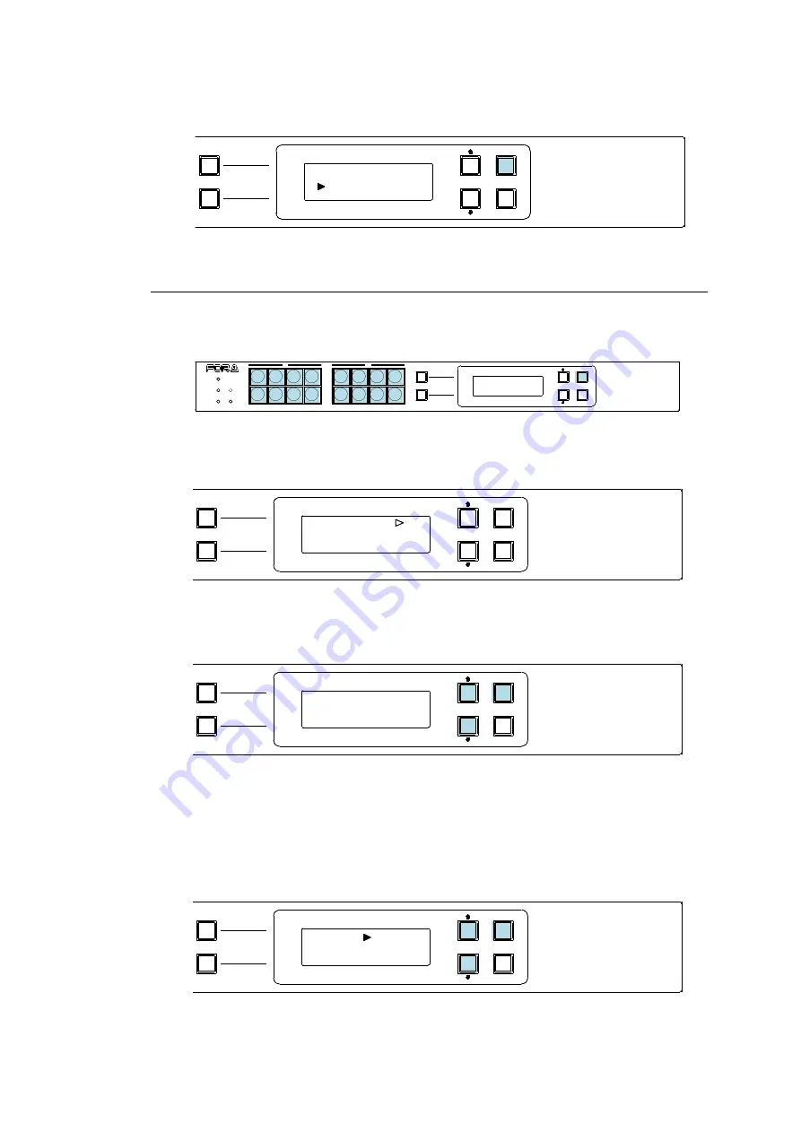
1. 

Press a button while holding down 

ENTER

. The button starts blinking. 


The  first  line  displays  the  button  function  and  its  currently  assigned  parameter.  The 
second line displays 

parameter’s detailed information. 


2. 

Press 

UP

  or 

DOWN

  to  select  a  function  to  be  assigned.  Press 

ENTER

  to  apply  the 

change. 


3. 

The display changes to the parameter selection according to the selected function. 
Press 

UP

 or 

DOWN

 to select the parameter value. Press 

ENTER

 to confirm the selection. 

The cursor will move to the next parameter if two or more parameters exist. Set the value 
and press 

ENTER

 in the same way, accordingly.  

Note that parameters keep blinking during the selection. 


When  all  settings  are  finished,  the  menu  display  automatically  returns  to  its  default 
display. 

PAGE A

(HOLD 3SEC)

PAGE B

LOCK

RESET

POWER

BUSY

SETUP

LOCK DEST

(HOLD 3SEC)

LOCK PANL

CANCEL

ENTER

A

B

MFR-16RUD

REMOTE CONTROL UNIT

DESTINATION 


  5 

[DST  5                    ] 

D


DST  5 


SRC  8 

PAGE A

(HOLD 3SEC)

PAGE B

LOCK

RESET

POWER

BUSY

SETUP

LOCK DEST

(HOLD 3SEC)

LOCK PANL

CANCEL

ENTER

A

B

MFR-16RUD

REMOTE CONTROL UNIT

PAGE A

(HOLD 3SEC)

PAGE B

LOCK

RESET

POWER

BUSY

SETUP

LOCK DEST

(HOLD 3SEC)

LOCK PANL

CANCEL

ENTER

A

B

MFR-16RUD

REMOTE CONTROL UNIT

SOURCE 

PAGE A

(HOLD 3SEC)

PAGE B

LOCK

RESET

POWER

BUSY

SETUP

LOCK DEST

(HOLD 3SEC)

LOCK PANL

CANCEL

ENTER

A

B

MFR-16RUD

REMOTE CONTROL UNIT

SOURCE 


    1 

[SRC  1  

  ] 

PAGE A

(HOLD 3SEC)

PAGE B

LOCK

RESET

POWER

BUSY

SETUP

LOCK DEST

(HOLD 3SEC)

LOCK PANL

CANCEL

ENTER

A

B

MFR-16RUD

REMOTE CONTROL UNIT

Содержание MFR-16

Страница 1: ...MFR RU Series MFR 16 40RU MFR 16RUD MFR 16 32 64RUW MFR 18RU RUA MFR 39RU RUA MFR 16RUTA MFR 8RUA Remote Control Unit 3rd Edition OPERATION MANUAL...

Страница 2: ...ion History Edit Rev Date Description Section Page 1 2017 08 23 First edition 2 2018 02 09 Throughout 3 2019 02 06 Added MFR 8RUA Added remote controller setting menu in the Web Based Control Througho...

Страница 3: ...round the unit to gas lines units or fixtures of an explosive or dangerous nature Operation Hazard Do not operate the unit under hazardous or potentially explosive atmospheric conditions Doing so coul...

Страница 4: ...d disconnect the power cord to avoid potentially hazardous conditions If problems similar to the above occur contact an authorized service representative before attempting to operate the unit again Ra...

Страница 5: ...MFR 16 32 64RUW 16RUTA is supplied w o Rack Mount Brackets Tool used to change button labels 1 LAN Cable straight 2 1 MFR 39 40 18RU 16RUTA 18RUA 39RUA 8RUA UTP cable 3m MFR 16RU 16RUD STP cable 3m MF...

Страница 6: ...t 30 5 2 4 Operating with CONTROL Rotary Selector 30 5 3 Function Buttons 33 5 4 MODE Button and Mode Menu MFR 18RU 18RUA 39RU 39RUA 16RUTA 8RUA 36 5 4 1 Outline 36 5 4 2 Mode Menu 37 5 4 3 Setting Mo...

Страница 7: ...hing Using a Bus Button 68 6 1 3 CHOP Function 69 6 1 4 Crosspoint Switching Using TAKE Function 69 6 2 Simultaneous Crosspoint Switching 70 6 2 1 Main Unit Stored Salvos 70 6 2 2 Remote Control Store...

Страница 8: ...RUD 85 8 2 4 MFR 16RUW 85 8 2 5 MFR 32RUW 86 8 2 6 MFR 64RUW 86 8 2 7 MFR 18RU 87 8 2 8 MFR 18RUA 87 8 2 9 MFR 39RU 88 8 2 10 MFR 39RUA 88 8 2 11 MFR 16RUTA 89 8 2 12 MFR 8RUA 89 Appendix Operation Ti...

Страница 9: ...gnable 32 MFR 64RUW 64 1 Color 3 4 Free Assignable 32 High end Model with LCD Display MFR 18RU 18 3 Colors 2 32 LCD Display at the top of each button 7 colors 7 letters x 2lines SRC and DEST button as...

Страница 10: ...s a main unit enter http 192 168 0 12 default 2 Login screen is displayed Input user name user and password password default IMPORTANT The MFR unit IP addresses login user name and password described...

Страница 11: ...mote Control Unit Image 4 Select 1 under Page 5 Select Destination under Function 6 Set parameters in the Parameter Setting pane Logical No Channel no Name Destination name and Level Level no are to b...

Страница 12: ...RE SET MFR 16RUW FUNC TION 1 2 REMOTE CONTROL UNIT MFR 32RUW POW ER BU SY SET UP LO CK RESET FUNCTION 1 2 REMOTE CONTROL UNIT MFR 32RUW MFR 64RUW MFR 6 4RUW REMOTECO NTROL UNIT 1 2 1 2 POWER BUSY LOC...

Страница 13: ...GE B MFR 8RUA POWER BUSY SETUP LOCK RESET REMOTE CONTROL UNIT MFR 8RUA D Button 1 7 Colors G CONTROL F MENU D Button 2 3 Colors B SETUP A C RESET H CANCEL E NAME DISPLAY D Button 2 3 Colors G CONTROL...

Страница 14: ...ssing the button switches Page 1 and Page 2 of Group A Button is unlit when Page 1 is current Button is lit orange when Page 2 is current To use the button as LOCK LOCAL press and hold down for 3 seco...

Страница 15: ...ANT After finishing settings do not power OFF the unit while BUSY LED is lit orange since the system is writing to Flash About 2 minutes max Changing Button Labels Button labels can be changed on user...

Страница 16: ...o connect the MFR main unit Ethernet port 10 100BASE TX B SERVICE Used for maintenance only Do not use C DC 12 V IN 1 2 Used to supply 12 V DC power D DC 12 V IN Used to supply 12 V DC power 1 The MFR...

Страница 17: ...e same locations on each page to the same setting Note that All Pages settings are disabled if button assignments are changed on a remote control unit The All Pages checkbox is changed to unchecked Fu...

Страница 18: ...in the table below Normal Hold 3sec LOCK OTHER NONE LOCAL LOCK ALL NONE LOCAL LOCK LOCAL NONE OTHER ALL NONE OTHER ALL LOCAL LOCK button 2 way button short or long press LOCK LOCAL button LOCK button...

Страница 19: ...select the unit to recall an MU Salvo or RU Salvo No Allows you to select the salvo number to recall For details on MU Salvo recall see Sec 4 5 Salvo Store SALVO button Salvo Store 2 Recall MU SALVO b...

Страница 20: ...by GUI 1 Click 19 to select a button 2 Select the LOCK type in the parameter screen See Function List on page 18 for details on the LOCK type 4 2 RU Info The RU Info page allows you to set remote con...

Страница 21: ...button brightness between Normal and Reduce dim light Function Source Destination Lock Page Button Color Level Button Tally Color LCD Color Sets the LCD Color for each function respectively Button Col...

Страница 22: ...mmediately after the Send button is clicked Page Sets the default page Last Page Displays the last page that was displayed when the RU was shutdown Select No A specified page is displayed as default B...

Страница 23: ...rrent MFR 39RUA page and LCD display of PAGE Jump buttons Button Color Allows PAGE Jump button colors to be set for each page 4 3 1 Saving and Loading the Settings File Allows you to save and load GUI...

Страница 24: ...rrent destination channel is 257 and over Copy does not function 6 Select the destination channels to save The selected channels are highlighted yellow 7 Click Entry The salvo is stored Clicking Cance...

Страница 25: ...5 1 CHOP function 6 1 3 TAKE function 6 1 4 Crosspoint change Simultaneous Main unit stored SALVO 6 2 1 RU button assigned SALVO 39 4 5 6 2 2 TAKE function 6 2 3 LINK function 6 2 4 Error prevention L...

Страница 26: ...4 4 4 BUTTON ASSIGN 2 Press buttons to execute functions Press a button to execute assigned function The button LED indication NAME DISPLAY and MENU display change according to the assigned function 5...

Страница 27: ...PANL A B REMOTE CONTROL UNIT MFR 16RU MFR 40RU POWER BUSY SETUP LOCK RESET MFR 40RU REMOTE CONTROL UNIT MFR 16RUD PAGE A HOLD 3SEC PAGE B LOCK RESET POWER BUSY SETUP LOCK DEST HOLD 3SEC LOCK PANL CAN...

Страница 28: ...bers are selectable for pages selected by Mode menu or Page buttons Excluding MFR 16RU 16RUD Maximum page number settings are applied to all groups Any page assignments or jumps are possible but do no...

Страница 29: ...ion page When assigning the signals select a level for respective signals to be assigned to the respective levels Selecting levels on remote control units The remote control unit can select channels o...

Страница 30: ...level number is indicated in the MENU or LCD display In the above case Ex 1 indicated as Level1 In the above case Ex 2 indicated as Level3 5 2 4 Operating with CONTROL Rotary Selector If your MFR Rem...

Страница 31: ...ment These units perform one of the following three operations set in the RU Settings page by selecting a Destination button Assign default Allows you to change the channel assignment of the selected...

Страница 32: ...L to confirm the change To cancel the change press the selected source button After confirming or canceling the change the button light returns to the previous state POWER BUSY SETUP LOCK RESET MFR 18...

Страница 33: ...tton 6 1 1 Bus Changes the destination channel source that is assigned to this button to the source channel assigned to this button 6 1 2 PAGE Changes pages to be displayed to a specified next or prev...

Страница 34: ...ssing a button for either a short or long time more than 3 seconds LOCK OTHER Disables control from external devices LOCK ALL Disables all controls LOCK LOCAL Disables local control NONE Assignable 2...

Страница 35: ...s Channel number increases in predetermined number 6 1 1 1 Channel number decreases in predetermined number Supported for MFR 18RU 18RUA 39RU 39RUA 16RUTA 8RUA Monitor Out Enables or disables the Moni...

Страница 36: ...Button and Mode Menu MFR 18RU 18RUA 39RU 39RUA 16RUTA 8RUA 5 4 1 Outline The MODE button allows you to switch Mode Menu By switching Mode Menu settings displayed MENU and LCD items and items using CO...

Страница 37: ...LCD Displays source channels for current destinations Current SRC button Displays the source channel of a current destination channel Turning CONTROL Changes source channel Pressing CONTROL applies th...

Страница 38: ...AGE UP DOWN Specified group pages move forward or backward MENU display LCD display Current PAGE display Setting Mode In MFR 39RU Displays settable menu titles Turn CONTROL to select a menu and change...

Страница 39: ...age to be displayed at remote control unit start up PAGE MODE UP DOWN JUMP Selects CONTROL behavior in Page mode UP DOWN Every turn of CONTROL changes the page one page forward or backward JUMP Turn a...

Страница 40: ...ttings may not be applied 5 4 3 1 NAME TYPE This menu selects a name display type for destination source and level buttons Turn and press CONTROL to select and confirm a button group from destination...

Страница 41: ...ange and returns to the menu display to select buttons Setting Function Parameters Function Parameter Note NONE DEST DEST XXX XXX Destination channel number LEVEL XXXX XXXX Level SRC SRC XXXX XXXX Sou...

Страница 42: ...RECALL MU RECALL Executes the main unit assigned SALVO RU RECALL Executes the button assigned SALVO RU STORE Assigns a SALVO to a button NO XXXX XXXX Salvo number Effective for MU RECALL and RU RECALL...

Страница 43: ...11 5 4 4 1 NETWORK The following submenus are available in NETWORK setting mode Submenu Description RU NETWORK Changes the remote control unit IP address and displays the network information PC LAN N...

Страница 44: ...mode PAGE ALL Page mode all groups PAGE GROUP A Page mode Group A PAGE GROUP B Page mode Group B PAGE GROUP C Page mode Group C PAGE GROUP D Page mode Group D SETTING Setting mode Pressing a button DE...

Страница 45: ...LEVEL Level Available level numbers are displayed BUS DESTINATION Destination channel SOURCE Source channel LEVEL Level Available level numbers are displayed PAGE TYPE JUMP Moves to the specified page...

Страница 46: ...number When TYPE is set to MU or RU 5 4 4 5 INHIBIT The following submenus are available in INHIBIT Setting mode Submenu Description DEST Sets INHIBIT to enabled disabled for a destination channels X...

Страница 47: ...e character code including 1 byte character code Not selectable for LEVEL BITMAP Bitmap image saved in the RU display When using 2 byte characters Up to 8 characters including one byte characters on M...

Страница 48: ...ssigns PAGE buttons to specified pages ALL PAGES Assigns PAGE buttons to all pages respectively Pressing a button DISPLAY Selects whether to display unit names for Current PAGE displays C D PAGE C D C...

Страница 49: ...ress the UP or DOWN button to display current destination DST 5 in this example 2 Press ENTER 3 The cursor automatically moves to the second line Source side Press UP or DOWN to select a source channe...

Страница 50: ...he cursor will move to the next parameter if two or more parameters exist Set the value and press ENTER in the same way accordingly Note that parameters keep blinking during the selection When all set...

Страница 51: ...Lock function by short press LOCKL XXX YYY Lock function by long press XXX OTH LOCK OTHER ALL LOCK ALL LOC LOCK LOCAL NON No lock YYY CUR Current Destination Destination Channel number YYY is effecti...

Страница 52: ...ress is set to 192 168 1 100 the eight 8 bit buttons display 192 128 64 by turning the light On or Off for each bit On On Off Off Off Off Off Off 4 Press the second button the second octet of buttons...

Страница 53: ...B then F Default Gateway 2 Press to select an octet button of buttons H The rightmost button represents the fourth octet See the previous page 3 The octet value is displayed on buttons I eight buttons...

Страница 54: ...e rightmost button of buttons I to turn on the button and change the octet value to 101 64 32 4 1 To change the first second or third octet value repeat steps 2 and 3 respectively To clear an octet va...

Страница 55: ...cting to MFR 4000 units MFR 16RU MFR 16RUD PAGE A HOLD 3SEC PAGE B LOCK RESET POWER BUSY SETUP LOCK DEST HOLD 3SEC LOCK PANL A B REMOTE CONTROL UNIT MFR 16RU MFR 40RU POWER BUSY SETUP LOCK RESET MFR 4...

Страница 56: ...net mask display Button B PC LAN on Main Unit MU IP address display Subnet mask display Default gateway display Button C PC LAN on Main Unit MU Reboot 5 7 1 Displaying Network Settings To Display RU I...

Страница 57: ...blinks Press and hold down SAVE to confirm the change The remote control unit automatically restarts To cancel the process press other button A C without pressing SAVE 5 7 3 Rebooting MU PC LAN 1 Pre...

Страница 58: ...NESS 1 dark 8 bright Sets the brightness for buttons LCD and the menu display BTN ASSIGN Assigns functions to buttons The same functions as those assignable in the Setting mode BTN ASSIGN menu are ava...

Страница 59: ...ode Menu MFR 39RUA See Sec 5 4 4 for details 5 10 Setup Menu MFR 16RUTA The SETUP button allows you to enter Setup Menu mode in which RU and MU PC LAN network settings are displayed the MU PC LAN port...

Страница 60: ...The IP address subnet mask and default gateway are successively displayed by pressing button D 5 10 2 Changing the RU Network Settings 1 Press SETUP to enter Setup Menu mode Press button A if other i...

Страница 61: ...which RU and MU PC LAN network settings are displayed the MU PC LAN port can be rebooted and RU network settings can be changed The left two buttons are used to select information to be displayed or t...

Страница 62: ...ETUP to display RU IP address Press button A if other information is displayed 2 Press and hold down the button under 100 The number blinks 3 Turn CONTROL to change the value to 101 To clear the numbe...

Страница 63: ...rd EXEC appears 3 Press and hold down the button under EXEC to reboot PC LAN The PC LAN and Startup messages are displayed during rebooting and disappears when the reboot is complete Disabled if conne...

Страница 64: ...ONTROL To enable or disable Lock functions LOCK LOCAL LOCK OTHER and LOCK ALL Lock functions in the multi panel operation All connected remote control units work as one remote control unit so LOCK LOC...

Страница 65: ...ss the CONTROL knob to select and confirm RU CONNECT Menu display 5 Turn and press the CONTROL knob to select and confirm ON MFR 39RUA Step Description Refer to 1 Press SETUP to enter the Setup Menu 2...

Страница 66: ...channel 8 The selected source button lights up The button with the source channel indication is highlighted Destination and source channels can also be selected using CONTROL or the display To select...

Страница 67: ...destination is 1 Pressing the SKIP FWD button selects destination channels 1 6 11 13 14 19 20 21 26 31 and so on Categories are user programmable source or destination channel groups They are set und...

Страница 68: ...NO INPUT START NO is 1 Select SRC A enter 3 on a Ten key keypad and press ENTER to select SRC 3 Select SRC B enter 5 on a Ten key keypad and press ENTER to select SRC 18 Ex 2 TENKEY MOD INPUT MODE is...

Страница 69: ...KE button to switch crosspoints Direct mode The TAKE function is always enabled Select crosspoints and press the TAKE button to switch crosspoints Ex 1 To use the Preset mode TAKE button Step Descript...

Страница 70: ...in Unit Stored Salvos This type of salvo allows you to store crosspoint data to be simultaneously switched into the routing switcher main unit The stored data can be recalled from any connected remote...

Страница 71: ...as shown below MFR 39RUA After completing the crosspoints assignments repress the SALVO button The Current DEST and SRC button displays change as shown below 4 MFR 39RU To add crosspoints to an existi...

Страница 72: ...n in the unit you are using or other units groups than those of the group units being used There are three types of Lock functions as shown in the chart below 6 3 1 LOCK LOCAL The Lock Local function...

Страница 73: ...unit that enabled the Lock function Lock functions can be disabled only from the unit that enabled the function In multi panel operation lock functions can be disabled from any remote control unit in...

Страница 74: ...ER function also enables Group LOCK OTHER which allows RU crosspoint switching only within the same group and locks RU crosspoint switching in other groups Any RU in the same group can lock or release...

Страница 75: ...channels to be easily monitored Enabling the Monitor Output Function The MONITOR OUT function is disabled as default To enable the function use the Monitor Output button on the remote control unit See...

Страница 76: ...4 3 2 BTN ASSIGN and 5 5 2 Changing Button Assignment Outputting the Operation Preview Press the O PREVIEW button on the remote control unit to output the preview signal from the set destination chann...

Страница 77: ...REEN or BLUE to ON press CONTROL to select RED GREEN or BLUE then turn CONTROL to select the color to ON 5 Press CONTROL to select ADJUST then turn CONTROL to adjust the selected color component 6 Pre...

Страница 78: ...To adjust the target button color using RED GREEN and BLUE press CONTROL to select RED GREEN or BLUE then turn CONTROL to change its value Setting range RED 0 3 GREEN and BLUE 0 7 5 To adjust other b...

Страница 79: ...o 240 V AC 11 VA 4 W MFR 16RUD 100 V AC to 120 V AC 8 VA 3 W 200 V AC to 240 V AC 11 VA 4 W Dimensions 430 W x 44 H x 34 D mm EIA 1 RU Weight 1 kg 8 1 2 MFR 40RU Buttons Colors 40 buttons 3 colors Red...

Страница 80: ...Interfaces MFR LAN 10 100BASE TX RJ 45 x 1 For connection to MU A network hub required for multiple unit configuration Temperature 0 C to 40 C Humidity 30 to 85 no condensation Power 12 VDC Pin conne...

Страница 81: ...V AC 12 VA 6 W 200 V AC to 240 V AC 18 VA 8 W Dimensions 430 W x 44 H x 42 D mm EIA 1 RU Weight 2 kg 8 1 7 MFR 18RUA Buttons Colors 18 buttons 3 colors Red Green Orange user assignable OLED display x...

Страница 82: ...VA 9 W 200 V AC to 240 V AC 22 VA 11 W Dimensions 430 W x 88 H x 44 D mm EIA 2 RU Weight 3 kg 8 1 9 MFR 39RUA Buttons Colors 39 buttons OLED buttons 7 color Displayed in each button Max 7 characters...

Страница 83: ...00 V AC to 240 V AC 15VA 6W Dimensions 215 W x 88 H x 43 D mm EIA 2 RU half rack size Weight 1 kg 8 1 11 MFR 8RUA Buttons Colors 8 buttons 3 colors Red Green Orange user assignable OLED display x 8 Ma...

Страница 84: ...480 44 32 6 6 6 4 REMOTE CONTROL UNIT M FR 16RU 34 DC12V IN MFR LAN 8 2 2 MFR 40RU All dimensions in mm 480 462 430 44 6 32 6 42 2 3 12 20 12 28 9 9 51 DC12V IN 2 1 SERVICE MFR LAN POWER BUSY LOCK SET...

Страница 85: ...SETUP LOCK DEST HOLD 3SEC LOCK PANL CANCEL ENTER A B 430 462 480 44 6 32 6 6 4 MFR 16RUD REMOTE CONTROL UNIT DC12V IN MFR LAN 34 8 2 4 MFR 16RUW All dimensions in mm 462 480 32 44 6 6 6 4 429 27 POWER...

Страница 86: ...DC12V I N 462 480 32 44 6 6 6 4 429 27 MFR LA N FUNCTION 1 2 REMOT E CONTRO L UNIT MFR 32RUW 8 2 6 MFR 64RUW All dimensions in mm RATING LA BE L DC12V I N MFR LA N 27 MFR 64RUW REMOTECO NTROL UNIT 1 2...

Страница 87: ...4 42 MFR LAN The panel buttons can be fitted within the rack by sliding the rack ears forward to attach as shown in the bottom figure above 8 2 8 MFR 18RUA All dimensions in mm POWER BUSY SETUP LOCK R...

Страница 88: ...FR LAN The panel buttons can be fitted within the rack by sliding the rack ears forward to attach as shown in the bottom figure above 8 2 10 MFR 39RUA All dimensions in mm POWER BUSY LOCK SETUP RESET...

Страница 89: ...RUTA REMOTE CONTROL UNIT LOCK POWER BUSY PAGE A LOCK SETUP RESET PAGE B 8 2 12 MFR 8RUA All dimensions in mm POWER BUSY SETUP LOCK RESET RESET LOCK BUSY POWER 2 1 SETUP 212 44 42 462 480 6 32 6 44 2 1...

Страница 90: ...ified page Ex Assign Page Jump between 3 and 7 for Group B C and D to Button 1 in the Web GUI 1 Click to select RU name Assign Function in the left pane to display the setting page 2 Select 1 under Bu...

Отзывы: