


Introduction and Specifications
Precision Analog Input (PAI) A/D Specifications
1
1-13
PAI A/D AC Voltage Measurement Specifications
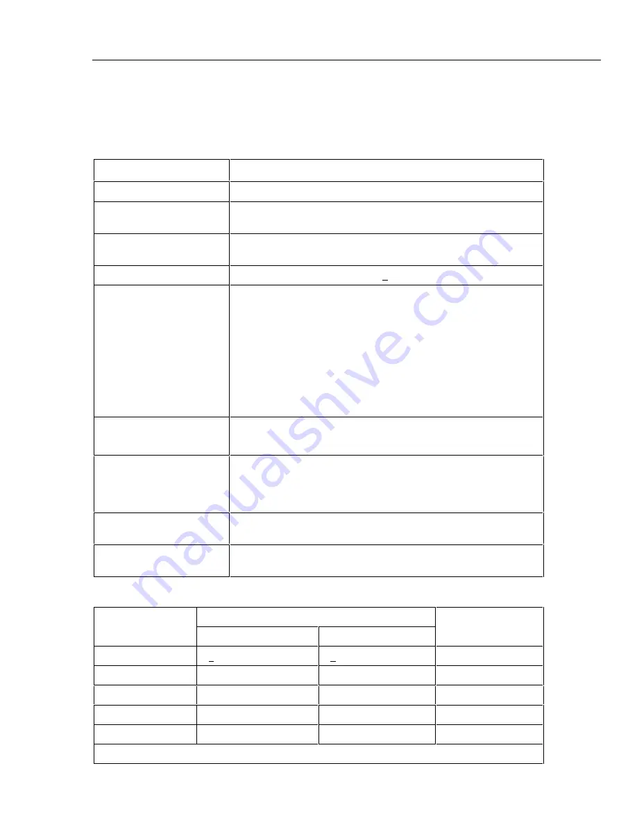
The following tables provide PAI A/D specifications for the ac voltage measurement
function.
Table 1-10. PAI A/D AC Voltage General Specifications
Specification
Characteristic
Input Impedance
1 M
Ω
in parallel with 100 pF
Maximum Crest Factor
3.0 Maximum
2.0 for rated accuracy
Crest Factor Error
For nonsinusoidal input signals with crest factors between 2 and 3 and
pulse widths >=100
µ
s, add 0.2% to the accuracy specifications.
Common Mode Rejection
80 dB minimum at dc, 50 Hz/60 Hz +0.1%, 1 k
Ω
imbalance, Slow Rate
Maximum Input Voltage
The lesser voltage of:
300 V ac rms from any terminal on channels 1 and 11 to earth.
150 V ac rms from any terminal on channels 2 through 10, and 12
through 20 to earth.
300 V ac rms from any terminal on channels 1 and 11 to any other
terminal.
150 V ac rms from any terminal on channels 2 through 10 and 12
through 20 to any other input terminal.
Maximum Volt-Hertz Product
2x10
6
Volt-Hertz product on any range, normal mode input.
1x10
6
Volt-Hertz product on any range, common mode input.
Temperature Coefficient
Linear interpolation between 2 applicable points for temperatures
between 28
°
C and 60
°
C, or -10
°
C and 18
°
C, e.g., if the applicable
specification at 28
°
C is 2% and the specification at 60
°
C is 3%, then
the specification at 40
°
C is (3%-2%)x(40-28)/(60-28)+2%=2.375%.
Accuracy at -20
°
C
Multiply the -10
°
C to +60
°
C accuracy specification by 2. After 1 hour
warm-up. For accuracy between -10
°
C and -20
°
C, interpolate linearly.
DC Component Error
The presence of a dc voltage will cause an indeterminate error in the
reading of the ac voltage on the input.
Table 1-11. PAI A/D AC Voltage Range and Resolution Specifications
Range
Resolution
Minimum Input for
Slow
Fast
Rate Accuracy
Full Scale
+30,000
+3,000
300 mV
10
µ
V
100
µ
V
20 mV
3 V
100
µ
V
1 mV
200 mV
30 V
1 mV
10 mV
2 V
150/300 V
10 mV
100 mV
20 V
Note 300 V range applies to channels 1 and 11 only.
Содержание 2680A
Страница 6: ......
Страница 12: ...268XA Service Manual vi ...
Страница 18: ...268XA Service Manual 1 2 ...
Страница 48: ...268XA Service Manual 1 32 ...
Страница 96: ...268XA Service Manual 2 48 ...
Страница 98: ...268XA Service Manual 3 2 ...
Страница 105: ...Maintenance DC Fuse Replacement 3 3 9 Fuse 4A 250V Slow 5MM X 20MM Bulk alg111f eps Figure 3 2 DC Fuse Location ...
Страница 106: ...268XA Service Manual 3 10 ...
Страница 132: ...268XA Service Manual 5 2 ...
Страница 194: ...268XA Service Manual 6 48 ...
Страница 195: ...7 1 Chapter 7 Replaceable Parts Title Page Introduction 7 3 How to Obtain Parts 7 3 Service Centers 7 3 Parts Lists 7 4 ...
Страница 196: ...268XA Service Manual 7 2 ...
Страница 204: ...268XA Service Manual 7 10 268X FINAL ASSEMBLY alg105f eps Figure 7 1 268XA Final Assembly ...
Страница 207: ...Replaceable Parts Parts Lists 7 7 13 2680A DIO alg100f eps Figure 7 3 DIO Module ...
Страница 209: ...Replaceable Parts Parts Lists 7 7 15 2680A FAI alg102f eps Figure 7 4 FAI Module ...
Страница 211: ...Replaceable Parts Parts Lists 7 7 17 2680A PAI alg103f eps Figure 7 5 PAI Module ...
Страница 214: ...268XA Service Manual 8 2 ...
Страница 215: ...8 3 8 Schematic Diagrams Figure 8 1 Backplane PCA 2680A 4001 ...
Страница 216: ...268XA Service Manual 8 4 Figure 8 1 Backplane PCA cont 2680A 1001 ...
Страница 217: ...8 5 8 Schematic Diagrams Figure 8 2 Controller System Power PCA 2680A 4004 ...
Страница 223: ...8 11 8 Schematic Diagrams Figure 8 3 Digital I O PCA 2680A 4006 ...
Страница 224: ...268XA Service Manual 8 12 Figure 8 3 Digital I O PCA cont 2680A 1006 1 of 3 ...
Страница 225: ...8 13 8 Schematic Diagrams Figure 8 3 Digital I O PCA cont 2680A 1006 2 of 3 ...
Страница 226: ...268XA Service Manual 8 14 Figure 8 3 Digital I O PCA cont 2680A 1006 3 of 3 ...
Страница 227: ...8 15 8 Schematic Diagrams Figure 8 4 Backplane Extender PCA 2680A 4009 ...
Страница 228: ...268XA Service Manual 8 16 Figure 8 4 Backplane Extender PCA cont 2680A 1009 ...
Страница 229: ...8 17 8 Schematic Diagrams Figure 8 5 Extender PCA 2680A 4010 ...
Страница 230: ...268XA Service Manual 8 18 Figure 8 5 Extender PCA cont 2680A 3010 ...
Страница 231: ...8 19 8 Schematic Diagrams Figure 8 6 A D Supply Assembly 2680A 4031 ...
Страница 232: ...268XA Service Manual 8 20 Figure 8 6 A D Supply Assembly cont 2680 1031 ...
Страница 233: ...8 21 8 Schematic Diagrams Figure 8 7 PCMCIA PCA 2680A 4041 ...
Страница 234: ...268XA Service Manual 8 22 Figure 8 7 PCMCIA PCA cont 2686 1041 ...
Страница 235: ...8 23 8 Schematic Diagrams Figure 8 8 Output PCA 2680A 4062 ...
Страница 236: ...268XA Service Manual 8 24 Figure 8 8 Output PCA cont 2680A 1062 ...
Страница 237: ...8 25 8 Schematic Diagrams Figure 8 9 A D PFE PCA 2640A 4003 ...
Страница 238: ...268XA Service Manual 8 26 Figure 8 9 A D PFE PCA cont 1 of 6 ...
Страница 239: ...8 27 8 Schematic Diagrams Figure 8 9 A D PFE PCA cont 2 of 6 ...
Страница 240: ...268XA Service Manual 8 28 Figure 8 9 A D PFE PCA cont 2640A 1003 3 of 6 ...
Страница 241: ...8 29 8 Schematic Diagrams Figure 8 9 A D PFE PCA cont 2640A 1003 4 of 6 ...
Страница 242: ...268XA Service Manual 8 30 Figure 8 9 A D PFE PCA cont 2640A 1003 5 of 6 ...
Страница 243: ...8 31 8 Schematic Diagrams Figure 8 9 A D PFE PCA cont 2640A 1003 6 of 6 ...
Страница 244: ...268XA Service Manual 8 32 Figure 8 10 A D FFE PCA 2645A 4003 ...
Страница 245: ...8 33 8 Schematic Diagrams Figure 8 10 A D FFE PCA cont 2645A 1003 1 of 6 ...
Страница 246: ...268XA Service Manual 8 34 Figure 8 10 A D FFE PCA cont 2645A 1003 2 of 6 ...
Страница 247: ...8 35 8 Schematic Diagrams Figure 8 10 A D FFE PCA cont 2645A 1003 3 of 6 ...
Страница 248: ...268XA Service Manual 8 36 Figure 8 10 A D FFE PCA cont 2645A 1003 4 of 6 ...
Страница 249: ...8 37 8 Schematic Diagrams Figure 8 10 A D FFE PCA cont 2645A 1003 5 of 6 ...
Страница 250: ...268XA Service Manual 8 38 Figure 8 10 A D FFE PCA cont 700p29_topress zip 2645A 1003 6 of 6 ...
Страница 251: ...8 39 8 Schematic Diagrams Figure 8 11 Analog Input Connector PCA 2620A 4004A ...
Страница 252: ...268XA Service Manual 8 40 2620A 1004 Figure 8 11 Analog Input Connector PCA cont ...
Страница 253: ...8 41 8 Schematic Diagrams Figure 8 12 Display PCA 1 of 1 ...
Страница 254: ...268XA Service Manual 8 42 Figure 8 12 Display PCA cont 1 of 1 ...


