


Performance Verification
Accuracy Performance Tests
4
4-11
Volts AC Accuracy Test
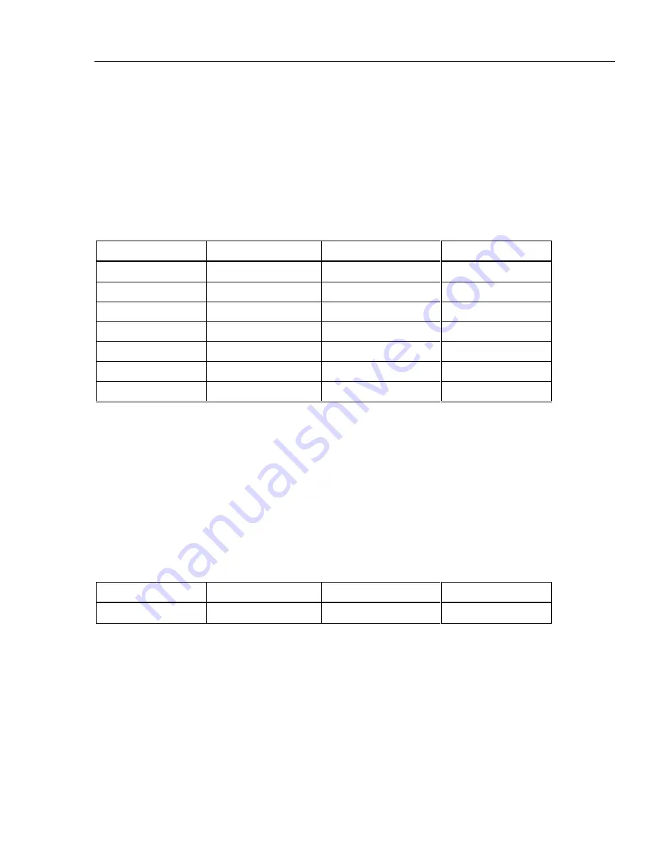
The following procedure tests the accuracy of the volts ac function for both the PAI and
FAI modules. Measurement accuracy applies to all channels, not just the channel used for
the test.
1.
Configure Channel 1 for V ac Using the Fluke DAQ software, configure channel 1
for V ac, 300 mV range.
2.
Open Spy Open the Spy window under the Configuration dialog.
3.
Verify Accuracy Configure the 5700A for the output values below and verify the
measurement is between the minimum and maximum values. Change the channel 1
range as required (see Step 1).
Volts AC Range
5700A Output
Minimum Reading
Maximum Reading
300 mV
20 mV@1 kHz
0.0197 V
0.0203 V
300 mV
20 mV@100 kHZ
0.0185 V
0.0215 V
300 mV
300 mV@1 kHz
0.29885 V
0.30115 V
300 mV
300 mV@100 kHz
0.2845 V
0.3155 V
3 V
3 V@1 kHz
2.9885 V
3.0115 V
30 V
30 V@1 kHz
29.885 V
30.115 V
300 V
300 V@1 kHz
298.85 V
301.15 V
Frequency Accuracy Test
The following procedure tests the accuracy of the frequency function for the PAI and FAI
modules. Measurement accuracy applies to all channels, not just the channel used for the
test.
1.
Configure Channel 1 for Frequency Using the Fluke DAQ software, configure
channel 1 for frequency. There is no range selection for frequency as all frequency
measurements use auto-ranging.
2.
Open Spy Open the Spy window under the Configuration dialog.
3.
Verify Accuracy Configure the 5700A for the output values below and verify the
measurement is between the minimum and maximum values. Change the channel 1
range as required (see Step 1).
Frequency Range
5700A Output
Minimum Reading
Maximum Reading
Autorange Only
1 V@10 kHz
9.994 kHz
10.006 kHz
Содержание 2680A
Страница 6: ......
Страница 12: ...268XA Service Manual vi ...
Страница 18: ...268XA Service Manual 1 2 ...
Страница 48: ...268XA Service Manual 1 32 ...
Страница 96: ...268XA Service Manual 2 48 ...
Страница 98: ...268XA Service Manual 3 2 ...
Страница 105: ...Maintenance DC Fuse Replacement 3 3 9 Fuse 4A 250V Slow 5MM X 20MM Bulk alg111f eps Figure 3 2 DC Fuse Location ...
Страница 106: ...268XA Service Manual 3 10 ...
Страница 132: ...268XA Service Manual 5 2 ...
Страница 194: ...268XA Service Manual 6 48 ...
Страница 195: ...7 1 Chapter 7 Replaceable Parts Title Page Introduction 7 3 How to Obtain Parts 7 3 Service Centers 7 3 Parts Lists 7 4 ...
Страница 196: ...268XA Service Manual 7 2 ...
Страница 204: ...268XA Service Manual 7 10 268X FINAL ASSEMBLY alg105f eps Figure 7 1 268XA Final Assembly ...
Страница 207: ...Replaceable Parts Parts Lists 7 7 13 2680A DIO alg100f eps Figure 7 3 DIO Module ...
Страница 209: ...Replaceable Parts Parts Lists 7 7 15 2680A FAI alg102f eps Figure 7 4 FAI Module ...
Страница 211: ...Replaceable Parts Parts Lists 7 7 17 2680A PAI alg103f eps Figure 7 5 PAI Module ...
Страница 214: ...268XA Service Manual 8 2 ...
Страница 215: ...8 3 8 Schematic Diagrams Figure 8 1 Backplane PCA 2680A 4001 ...
Страница 216: ...268XA Service Manual 8 4 Figure 8 1 Backplane PCA cont 2680A 1001 ...
Страница 217: ...8 5 8 Schematic Diagrams Figure 8 2 Controller System Power PCA 2680A 4004 ...
Страница 223: ...8 11 8 Schematic Diagrams Figure 8 3 Digital I O PCA 2680A 4006 ...
Страница 224: ...268XA Service Manual 8 12 Figure 8 3 Digital I O PCA cont 2680A 1006 1 of 3 ...
Страница 225: ...8 13 8 Schematic Diagrams Figure 8 3 Digital I O PCA cont 2680A 1006 2 of 3 ...
Страница 226: ...268XA Service Manual 8 14 Figure 8 3 Digital I O PCA cont 2680A 1006 3 of 3 ...
Страница 227: ...8 15 8 Schematic Diagrams Figure 8 4 Backplane Extender PCA 2680A 4009 ...
Страница 228: ...268XA Service Manual 8 16 Figure 8 4 Backplane Extender PCA cont 2680A 1009 ...
Страница 229: ...8 17 8 Schematic Diagrams Figure 8 5 Extender PCA 2680A 4010 ...
Страница 230: ...268XA Service Manual 8 18 Figure 8 5 Extender PCA cont 2680A 3010 ...
Страница 231: ...8 19 8 Schematic Diagrams Figure 8 6 A D Supply Assembly 2680A 4031 ...
Страница 232: ...268XA Service Manual 8 20 Figure 8 6 A D Supply Assembly cont 2680 1031 ...
Страница 233: ...8 21 8 Schematic Diagrams Figure 8 7 PCMCIA PCA 2680A 4041 ...
Страница 234: ...268XA Service Manual 8 22 Figure 8 7 PCMCIA PCA cont 2686 1041 ...
Страница 235: ...8 23 8 Schematic Diagrams Figure 8 8 Output PCA 2680A 4062 ...
Страница 236: ...268XA Service Manual 8 24 Figure 8 8 Output PCA cont 2680A 1062 ...
Страница 237: ...8 25 8 Schematic Diagrams Figure 8 9 A D PFE PCA 2640A 4003 ...
Страница 238: ...268XA Service Manual 8 26 Figure 8 9 A D PFE PCA cont 1 of 6 ...
Страница 239: ...8 27 8 Schematic Diagrams Figure 8 9 A D PFE PCA cont 2 of 6 ...
Страница 240: ...268XA Service Manual 8 28 Figure 8 9 A D PFE PCA cont 2640A 1003 3 of 6 ...
Страница 241: ...8 29 8 Schematic Diagrams Figure 8 9 A D PFE PCA cont 2640A 1003 4 of 6 ...
Страница 242: ...268XA Service Manual 8 30 Figure 8 9 A D PFE PCA cont 2640A 1003 5 of 6 ...
Страница 243: ...8 31 8 Schematic Diagrams Figure 8 9 A D PFE PCA cont 2640A 1003 6 of 6 ...
Страница 244: ...268XA Service Manual 8 32 Figure 8 10 A D FFE PCA 2645A 4003 ...
Страница 245: ...8 33 8 Schematic Diagrams Figure 8 10 A D FFE PCA cont 2645A 1003 1 of 6 ...
Страница 246: ...268XA Service Manual 8 34 Figure 8 10 A D FFE PCA cont 2645A 1003 2 of 6 ...
Страница 247: ...8 35 8 Schematic Diagrams Figure 8 10 A D FFE PCA cont 2645A 1003 3 of 6 ...
Страница 248: ...268XA Service Manual 8 36 Figure 8 10 A D FFE PCA cont 2645A 1003 4 of 6 ...
Страница 249: ...8 37 8 Schematic Diagrams Figure 8 10 A D FFE PCA cont 2645A 1003 5 of 6 ...
Страница 250: ...268XA Service Manual 8 38 Figure 8 10 A D FFE PCA cont 700p29_topress zip 2645A 1003 6 of 6 ...
Страница 251: ...8 39 8 Schematic Diagrams Figure 8 11 Analog Input Connector PCA 2620A 4004A ...
Страница 252: ...268XA Service Manual 8 40 2620A 1004 Figure 8 11 Analog Input Connector PCA cont ...
Страница 253: ...8 41 8 Schematic Diagrams Figure 8 12 Display PCA 1 of 1 ...
Страница 254: ...268XA Service Manual 8 42 Figure 8 12 Display PCA cont 1 of 1 ...


