


268XA
Service Manual
6-6
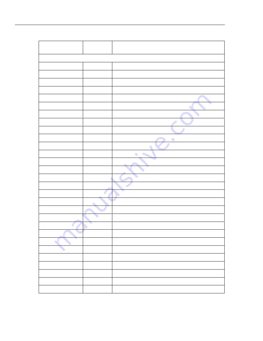
Table 6-1. Self-Test Error Codes (cont)
Front Panel Err
Self-test
Code
Description
Second 32-bit self-test code
0x00000000
No self-test error.
32
0x00000001
Module 3 Calibration constants corrupt
33
0x00000002
Module 3 Calibration Procedures Incomplete
34
0x00000004
Module 3 A/D failure
35
0x00000008
Module 3 Zero offset measurements unreasonable
36
0x00000010
Module 3 Reference balance measurements unreasonable
37
0x00000020
Module 3 Overload detection failed
38
0x00000040
Module 3 Open thermocouple detection failed
39
0x00000080
Module 4 Calibration constants corrupt
40
0x00000100
Module 4 Calibration Procedures Incomplete
41
0x00000200
Module 4 A/D failure
42
0x00000400
Module 4 Zero offset measurements unreasonable
43
0x00000800
Module 4 Reference balance measurements unreasonable
44
0x00001000
Module 4 Overload detection failed
45
0x00002000
Module 4 Open thermocouple detection failed
46
0x00004000
Module 5 Calibration constants corrupt
47
0x00008000
Module 5 Calibration Procedures Incomplete
48
0x00010000
Module 5 A/D failure
49
0x00020000
Module 5 Zero offset measurements unreasonable
50
0x00040000
Module 5 Reference balance measurements unreasonable
51
0x00080000
Module 5 Overload detection failed
52
0x00100000
Module 5 Open thermocouple detection failed
53
0x00200000
Module 6 Calibration constants corrupt
54
0x00400000
Module 6 Calibration Procedures Incomplete
55
0x00800000
Module 6 A/D failure
56
0x01000000
Module 6 Zero offset measurements unreasonable
57
0x02000000
Module 6 Reference balance measurements unreasonable
58
0x04000000
Module 6 Overload detection failed
59
0x08000000
Module 6 Open thermocouple detection failed
Содержание 2680A
Страница 6: ......
Страница 12: ...268XA Service Manual vi ...
Страница 18: ...268XA Service Manual 1 2 ...
Страница 48: ...268XA Service Manual 1 32 ...
Страница 96: ...268XA Service Manual 2 48 ...
Страница 98: ...268XA Service Manual 3 2 ...
Страница 105: ...Maintenance DC Fuse Replacement 3 3 9 Fuse 4A 250V Slow 5MM X 20MM Bulk alg111f eps Figure 3 2 DC Fuse Location ...
Страница 106: ...268XA Service Manual 3 10 ...
Страница 132: ...268XA Service Manual 5 2 ...
Страница 194: ...268XA Service Manual 6 48 ...
Страница 195: ...7 1 Chapter 7 Replaceable Parts Title Page Introduction 7 3 How to Obtain Parts 7 3 Service Centers 7 3 Parts Lists 7 4 ...
Страница 196: ...268XA Service Manual 7 2 ...
Страница 204: ...268XA Service Manual 7 10 268X FINAL ASSEMBLY alg105f eps Figure 7 1 268XA Final Assembly ...
Страница 207: ...Replaceable Parts Parts Lists 7 7 13 2680A DIO alg100f eps Figure 7 3 DIO Module ...
Страница 209: ...Replaceable Parts Parts Lists 7 7 15 2680A FAI alg102f eps Figure 7 4 FAI Module ...
Страница 211: ...Replaceable Parts Parts Lists 7 7 17 2680A PAI alg103f eps Figure 7 5 PAI Module ...
Страница 214: ...268XA Service Manual 8 2 ...
Страница 215: ...8 3 8 Schematic Diagrams Figure 8 1 Backplane PCA 2680A 4001 ...
Страница 216: ...268XA Service Manual 8 4 Figure 8 1 Backplane PCA cont 2680A 1001 ...
Страница 217: ...8 5 8 Schematic Diagrams Figure 8 2 Controller System Power PCA 2680A 4004 ...
Страница 223: ...8 11 8 Schematic Diagrams Figure 8 3 Digital I O PCA 2680A 4006 ...
Страница 224: ...268XA Service Manual 8 12 Figure 8 3 Digital I O PCA cont 2680A 1006 1 of 3 ...
Страница 225: ...8 13 8 Schematic Diagrams Figure 8 3 Digital I O PCA cont 2680A 1006 2 of 3 ...
Страница 226: ...268XA Service Manual 8 14 Figure 8 3 Digital I O PCA cont 2680A 1006 3 of 3 ...
Страница 227: ...8 15 8 Schematic Diagrams Figure 8 4 Backplane Extender PCA 2680A 4009 ...
Страница 228: ...268XA Service Manual 8 16 Figure 8 4 Backplane Extender PCA cont 2680A 1009 ...
Страница 229: ...8 17 8 Schematic Diagrams Figure 8 5 Extender PCA 2680A 4010 ...
Страница 230: ...268XA Service Manual 8 18 Figure 8 5 Extender PCA cont 2680A 3010 ...
Страница 231: ...8 19 8 Schematic Diagrams Figure 8 6 A D Supply Assembly 2680A 4031 ...
Страница 232: ...268XA Service Manual 8 20 Figure 8 6 A D Supply Assembly cont 2680 1031 ...
Страница 233: ...8 21 8 Schematic Diagrams Figure 8 7 PCMCIA PCA 2680A 4041 ...
Страница 234: ...268XA Service Manual 8 22 Figure 8 7 PCMCIA PCA cont 2686 1041 ...
Страница 235: ...8 23 8 Schematic Diagrams Figure 8 8 Output PCA 2680A 4062 ...
Страница 236: ...268XA Service Manual 8 24 Figure 8 8 Output PCA cont 2680A 1062 ...
Страница 237: ...8 25 8 Schematic Diagrams Figure 8 9 A D PFE PCA 2640A 4003 ...
Страница 238: ...268XA Service Manual 8 26 Figure 8 9 A D PFE PCA cont 1 of 6 ...
Страница 239: ...8 27 8 Schematic Diagrams Figure 8 9 A D PFE PCA cont 2 of 6 ...
Страница 240: ...268XA Service Manual 8 28 Figure 8 9 A D PFE PCA cont 2640A 1003 3 of 6 ...
Страница 241: ...8 29 8 Schematic Diagrams Figure 8 9 A D PFE PCA cont 2640A 1003 4 of 6 ...
Страница 242: ...268XA Service Manual 8 30 Figure 8 9 A D PFE PCA cont 2640A 1003 5 of 6 ...
Страница 243: ...8 31 8 Schematic Diagrams Figure 8 9 A D PFE PCA cont 2640A 1003 6 of 6 ...
Страница 244: ...268XA Service Manual 8 32 Figure 8 10 A D FFE PCA 2645A 4003 ...
Страница 245: ...8 33 8 Schematic Diagrams Figure 8 10 A D FFE PCA cont 2645A 1003 1 of 6 ...
Страница 246: ...268XA Service Manual 8 34 Figure 8 10 A D FFE PCA cont 2645A 1003 2 of 6 ...
Страница 247: ...8 35 8 Schematic Diagrams Figure 8 10 A D FFE PCA cont 2645A 1003 3 of 6 ...
Страница 248: ...268XA Service Manual 8 36 Figure 8 10 A D FFE PCA cont 2645A 1003 4 of 6 ...
Страница 249: ...8 37 8 Schematic Diagrams Figure 8 10 A D FFE PCA cont 2645A 1003 5 of 6 ...
Страница 250: ...268XA Service Manual 8 38 Figure 8 10 A D FFE PCA cont 700p29_topress zip 2645A 1003 6 of 6 ...
Страница 251: ...8 39 8 Schematic Diagrams Figure 8 11 Analog Input Connector PCA 2620A 4004A ...
Страница 252: ...268XA Service Manual 8 40 2620A 1004 Figure 8 11 Analog Input Connector PCA cont ...
Страница 253: ...8 41 8 Schematic Diagrams Figure 8 12 Display PCA 1 of 1 ...
Страница 254: ...268XA Service Manual 8 42 Figure 8 12 Display PCA cont 1 of 1 ...


