
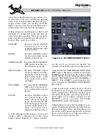


EXTERIOR LIGHTING
The exterior lighting systems consist of the
landing lights, taxi lights, recognition lights,
navigation lights, anticollision (beacon/strobe)
lights, wing inspection light, and optional logo
and exterior convenience lights (Figure 3-13).
LANDING-TAXI LIGHTS
The landing lights consist of two dual bulb
light assemblies mounted just forward of the
wing fuselage fairing (Figure 3-14). The taxi
lights consist of a single filament light mounted
on each main landing gear strut (Figure 3-15).
When the LDG - TAXI lights switches are
placed to the TAXI position, the taxi light on
each main gear strut illuminates if that main
gear is down and locked. When these switches
are placed to the LDG (landing) position, the
taxi lights remain illuminated and the landing
lights under the fuselage illuminate. The gear
does not have to be down for the landing lights
to work. The landing lights consist of two
bulbs in an assembly under the right side of
the fuselage and two bulbs in an assembly
under the left side of the fuselage. The out-
board bulb in each assembly also serve as
recognition lights when the landing lights are
not turned on.
The landing/taxi lights are powered from the
left and right main busses, respectively and
are protected by circuit breakers labeled “L
and R TAXI/LDG CTRL” located on the pilot
and copilot circuit breaker panels in the
LIGHTS group.
RECOGNITION LIGHTS
Recognition lights consist of the outboard
bulbs of the landing light assemblies. Moving
the RECOG toggle switch on the light control
panel up (Figure 3-13) illuminates both out-
board landing bulbs. When the landing lights
are turned on, the recognition bulbs illuminate
even when the RECOG switch is off. The
recognition lights receive power from the re-
spective left and right generator busses and use
control power from the respective left and
r i g h t m a i n bu s s e s t h r o u g h t h e L a n d R
TAXI/LDG CTRL circuit breaker. When
equipped with the pulse light option, the
RECOG switch is modified to include a
PULSE position.
NAVIGATION LIGHTS
The navigation lights system consists of three
lights: two wing-tip (winglet) position lights
and one tail mounted position light that is
viewable from the rear (Figures 3-13, 3-16
and 3-17).
All three navigation lights are controlled by
t h e NAV l i g h t s w i t c h ( F i g u r e 3 - 1 3 ) .
Additionally, setting the NAV light switch to
NAV (or to NAV/LOGO) automatically dims
all cockpit switch/indicator lights on the in-
strument panel and the center pedestal. The
NAV switch is a two position (OFF-NAV) on
airplanes not equipped with the optional
LOGO lights. When equipped with the LOGO
lights, a third position (NAV/LOGO) is added
to the NAV light switch.
The navigation lights receive 28 VDC power
from the right main bus and are protected by
the “NAV” circuit breaker located on the copi-
lot circuit breaker panel within the LIGHTS
group.
TAIL LOGO LIGHTS
(OPTIONAL)
Optional tail logo lights consist of two lights
installed on the bottom of the horizontal sta-
bilizer that illuminate both sides of the verti-
cal stabilizer. Controlled by a LOGO position
on the NAV light switch, they are powered by
the right non-essential bus. The logo lights are
protected by the “LOGO” circuit breaker lo-
cated on the copilot circuit breaker panel
within the CABIN group.
L E A R J E T 4 5
P I L O T T R A I N I N G M A N U A L
3-12
FOR TRAINING PURPOSES ONLY
FlightSafety
international