


SPLIT BUS SYSTEM
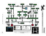
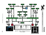
The split bus electrical system (Figure 2-17)
has a left and right generator bus (GEN BUS)
located in a left and right power distribution
panel (PDP) in the tailcone. The generator
busses supply power to the respective left and
right essential, left and right main, and left
and right non-essential busses located on the
left and right circuit breaker panels in the cock-
pit. Under normal flight conditions, the gen-
erator busses are split (bus-tie open), increasing
safety in that any major electrical system fault
will only affect one side of the system.
GENERATOR BUSSES
The generator busses are the central distribu-
tion point for the split-bus system. The left gen-
erator bus powers the left side busses and the
right generator bus powers the right side
busses. Some services including landing lights,
taxi lights, navigation lights, recognition lights
and baggage heat are connected through fuses
and circuit breakers directly to the generator
busses. Each generator bus is connected to a
starter/generator and a main battery. The GPU
connects to the left generator bus and the APU
(if installed) connects to the right generator
bus. Normally, the two busses operate inde-
pendently; however, they are automatically
“tied” through a bus-tie contactor when a GPU
or APU is connected to the electrical system,
during engine starting and inflight following
a single generator failure. The generator busses
can be tied or split manually using the bus-tie
switch on the electrical control panel, except
the bus-tie cannot be manually opened when
a GPU is being used.
The CAS presents a “BUS TIE CLSD” mes-
sage when the bus-tie is closed and a “BUS TIE
MANUAL” message when closed or opened
manually. Also, the bar on the bus-tie switch
illuminates any time the bus-tie is closed and
it extinguishes when the bus-tie is open.
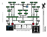
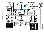
MAIN BUSSES
The left and right main busses are fed by the
respective left and right generator busses
through fuses and contactors (Figure 2-17).
The main busses, in turn, supply power to the
left and right main avionics busses through cir-
cuit breakers and contactors. Both of the main
busses are automatically disconnected in the
event of a dual generator failure and the OFF
caption will illuminate on the main bus
switches. The main avionics busses will also
be depowered in this case, but the OFF cap-
tion does not illuminate on the avionics mas-
ter switches since the essential avionics busses
will still be powered. The main busses and
main avionic busses may be reconnected by
manual selection after reducing the load, but
doing so will significantly reduce the battery
duration after a dual generator failure.
MAIN AVIONICS BUSSES
The left and right main avionics busses are
supplied by the respective main busses through
contactors and circuit breakers (Figure 2-17).
The essential and main avionics bus contactors
are closed and opened by manual selection of
the left and right avionics master switches. If
the avionics master switches are on, the main
avionics busses are automatically depowered
during engine start to prevent possible equip-
ment damage due to voltage spikes.
The essential avionics busses remain pow-
ered by the emergency battery during engine
start since they power flight critical display
units. The avionics master switches need not
be on during ground start since the primary
flight displays are not needed and DU2
(EICAS) is still powered with the avionics
master switches OFF.
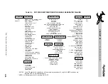
ESSENTIAL BUSSES
All essential power loads are connected to
these two busses, including cockpit warning
systems and the engine, flap, hydraulic, pres-
surization, and spoiler controls (Table 2-4).
Normally, the essential busses (Figure 2-17) are
L E A R J E T 4 5
P I L O T T R A I N I N G M A N U A L
2-24
FOR TRAINING PURPOSES ONLY
FlightSafety
international