


Flap Position Selector
The flap selector is located on the aft right side
of the throttle quadrant (Figure 15-18). The se-
lector has four positions (UP, 8°, 20°, and DN)
with detents at the 8° and 20° positions. When
retracting the flaps, there is a gate at the 8° po-
sition. The selector must be pulled out slightly
to raise it above that setting.
The selector is attached to a RVDT located
within the throttle quadrant which transmit
selected position to the flap control unit. Also,
located in the throttle quadrant is a flap lever
detent switch (Figure 15-17). Moving the flap
selector between positions will actuate the
switch and energize a time-delay relay, which,
in turn, energizes the arming solenoid valve
within the flap power unit. This circuit stays
energized for 75 seconds and then depowers
(closes) the arming solenoid valve. Normal
flap extension from 0° to 40° will not exceed
20 seconds with engine driven hydraulic pumps
operating. When using HYD XFLOW however,
it can take up to 60 seconds to lower the flaps
from 0° to 20° inflight. The maximum flap
extension called for by the AFM when using
HYD XFLOW is 20°.
Flap Indications
The flap position indicating unit (Figure 15-
17) has two separate and independent channels
(channel 1 for left side equipment and chan-
nel 2 for right side equipment) housed in a
common chassis. A separate RVDT supplies
flap position information for each channel. A
failure in one channel will not affect the op-
eration of the other channel. Figure 15-17 il-
lustrates some, but not all, of the airplane
systems that flap position information is pro-
vided to.
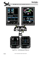
Flap position has a full-time digital display on
the EICAS, below the CAS window (Figure 15-
15). The digital display on the EICAS will
have a white box around it anytime the flaps
are not in the selected position and also any-
time the airplane is on the ground and the
flaps are not set for takeoff (8° or 20°). The
display turns red and an aural “Configuration”
voice message is broadcast if power is ad-
vanced to MCR or above for takeoff and the
flaps are not set properly. The display turns
amber if there is a fault or failure in the flap
system.
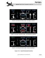
Flap selection and position indications are also
displayed on the right side of the FLT (flight)
system schematic page (Figure 15-16). The
FLT system schematic can be called up for
display on the EICAS or MFD.
Flap selected position is indicated with a hor-
izontal magenta line across the vertical scale
and the left and right flap position indicators
are pointers on each side of the vertical scale.
When the flaps have moved to the selected po-
sition, the pointers should overlay the magenta
line. Like the digital flap position indication,
the flap position pointers turn red if the airplane
is on the ground and power is advanced to
MCR or above with the flaps set at other than
8° or 20°. Also, the pointers turn amber if there
is a fault/failure in the flap system.
A digital indication of flap position is also
provided on the engine page on the RMU
(Figure 15-15).
15-23
FOR TRAINING PURPOSES ONLY
L E A R J E T 4 5
P I L O T T R A I N I N G M A N U A L
FlightSafety
international
Figure 15-18. Flap Selector