


Annex
DYNAVERT
®
L05
58
Stand/ issue: 25.07.03
4BS0516DE-EN/011
7.5 Definitions
Setting speed:
The lift speed is controlled by the motor speed, dependent from traction sheave diameter, gear ratio and
roping. The particular advantage of the frequency inverters in this connection is, that these conditions
are not bound to the fixed speed of a motor powered directly from the mains.
In most cases, the speed stamped on the motor type plate is not identical with
the set speed that is to be entered in parameter v/n in menu P-SYSTEM DATA.
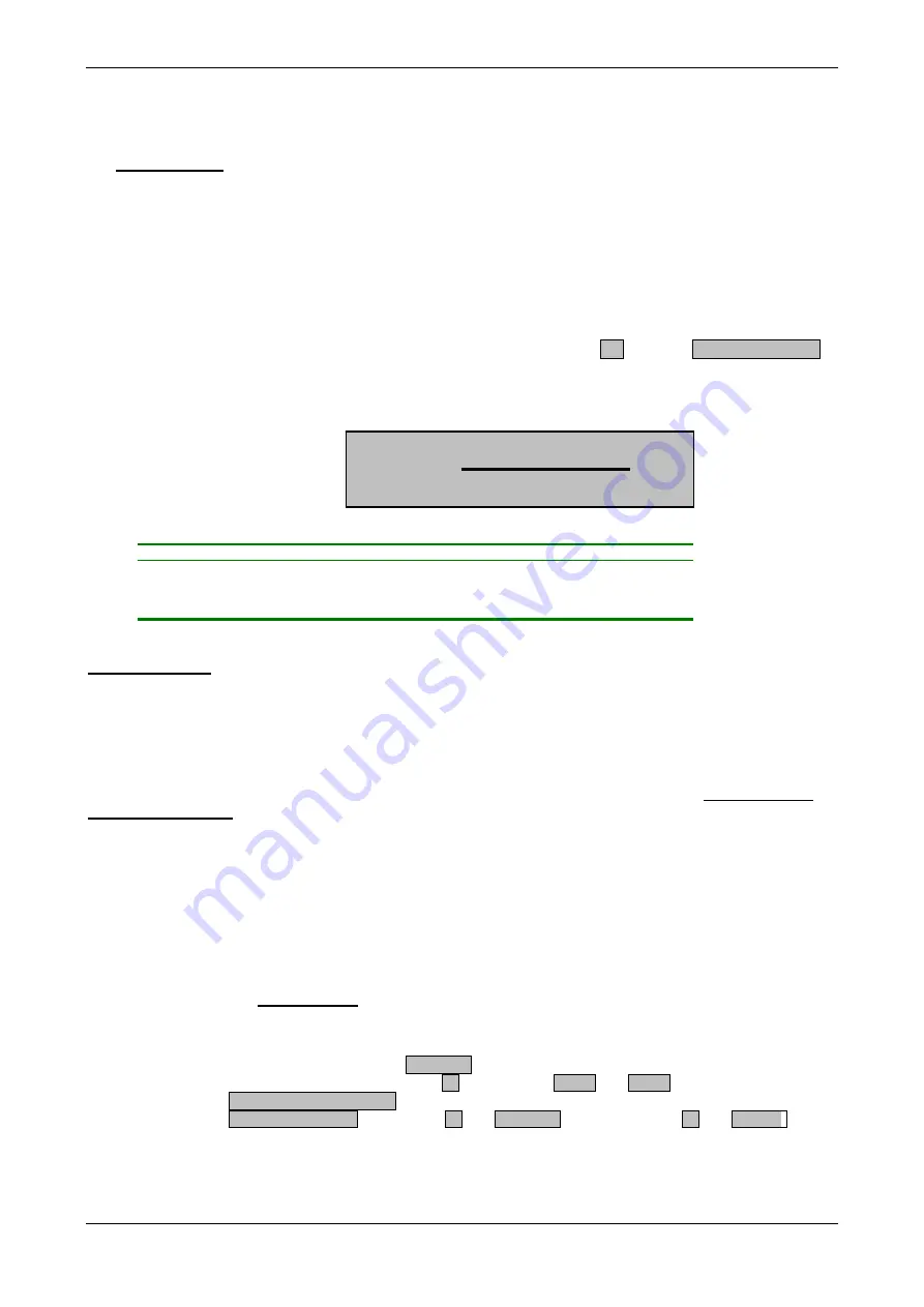
The
setting speed
n
Set
can be established according to the following formula:
19,1 * v * r
n
Set
=
d * i
n
Setting
=
the parameter value to be set for the setting speed
v
=
operating speed of the lift in m/s
d
=
traction sheave diameter in m
i
=
gear ratio from the type plate of the gear
r
=
roping:
1
if roping 1:1 resp.
2
if roping 2:1
Position control:
Contrary to the usual travelling curve control using the motor speed, Dynavert
®
L05-devices are provided with
a position control. The software calculates the time-optimized travelling sequence by means of a speed
sensor using the online-position calculation, considering the parameterised values of the travel curve.
With or without positioning run, the repeated accurate approach and levelling of the lift is herewith ensured.
The important advantage of the position control lies in the fact that always the permanent
time-optimized
travelling sequence
is calculated in conformity with the travel curve data. This applies also when the
operating speed is not reached on a trip from one floor to the next. In this case, an optimal ogival travel is
made.The deceleration is always initiated at a distance optimal to the destination floor.
In order to maintain these properties of the Dynavert
®
L05 during operation, the following simple rule for the
adjustment shall be observed upon setting of the deceleration distances.
The stoppage point (braking vane) required for the control to stop the lift at a landing,
must always be more distant, or at least equally distant from the level position as the
min. braking distance for the actually set speed, deceleration and jerk x.
This min.braking distance BrkDis v3 is calculated by the inverter by means of the
parameterised values for speed v3, deceleration Decel. and Jerk x (in menu
P-TRAVEL KURVE DATA) and can be read out via information menu
I-MIN.BRAKE.DIST. (applies for v1 and BrkDis v1 accordingly, also v2 and BrkDis )


