eCO Premium™ - Installation & Maintenance
28
FläktGroup DC_9604GB_20190327_R6
Specifications are subject to alteration without notice
By replacing the extract temperature sensor with a room temper-
ature sensor placed in the room in question, a good room tem-
perature value is achieved.
This enables the unit to regulate the supply air temperature in a
way that maintains the room temperature at a desired level.
Limitation of the supply air temperature (min. temp. and max.
temp.) ensures that the supply air temperature is maintained
within the set range.
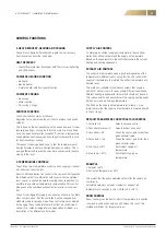
DEFAULT PARAMETERS FOR ROOM CONTROL
1. Controller = 2
Selects cascade control
2. Cascade reference = 0
Selects room control
3. Cascade A = 0.5
When the sensor gets colder than
given setpoint value
4. Cascade B = –0.5
When the sensor gets hotter than
given setpoint value
5. Min. temp. = 15°C
Sets lowest supply air
temperature
6. Max. temp. = 25°C
Sets highest supply air temperature
EXAMPLE
1. Setpoint = 18°C
2. Room temperature = 22°
This means that the new calculated setpoint for the supply air
controller is: Calculated setpoint = se (setpoint – room air
temperature) x cascade B = 18 – (18 – 22) x (–0.5) = 16°C.
OUTDOOR TEMPERATURE COMPENSATION
The setpoint temperature for supply air can be adjusted up or
down depending on the outdoor temperature. By setting a higher
set point value both on cold winter days and hot summer days
indoors comfort is improved.
In summer, this will increase energy savings. Outdoor tempera-
ture compensation can not be combined with extract air control
or room control.
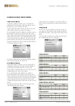
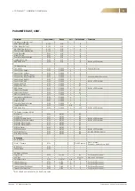
DEFAULT PARAMETERS FOR OUTDOOR TEMPERATURE
COMPENSATION
1. Controller = 2
Selects cascade control.
2. Cascade reference = 1 Selects outdoor temperature com-
pensation.
3. Cascade A = 0,05
When the sensor gets colder than
given setpoint value.
4. Cascade B = 0.03
When the sensor gets hotter than
given setpoint value.
5. Min. temp. = 15°C
Sets lowest supply air
temperature.
6. Max. temp. = 25°C
Sets highest supply air temperature.
CONTROL FUNCTIONS (CONT.)
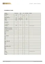
Setpoint
Outdoor temperature compensation
Outdoor temperature, °C
+30
+25
+20
+15
35
30
25
20
15
10
5
0
–5
–10
–15
–20
EXAMPLE 1
1. Setpoint = 18°C
2. Outdoor air temperature = –2°C
This means that the new calculated setpoint for the supply air
controller is:
Calculated setpoint = se (setpoint – outdoor air tempera-
ture) x cascade A = 18 + (18 –(-2)) x 0.05 = 19°C
EXAMPLE 2
1. Setpoint = 18°C
2. Outdoor air temperature = 28°C
This means that the new calculated setpoint for the supply air
controller is:
Calculated setpoint = se (setpoint – outdoor air tempera-
ture) x cascade B = 18 – (18 – 28)) x 0.30 = 21°C.
3. FROST PROTECTION
Warning! Do not change these parameters unless it is absolutely
necessary. If the unit is misconfigured the water coil can freeze
and cause water damage to property.
Frost protection is used during low outdoor temperatures to
prevent the coil from freezing. When the unit is stopped, the tem-
perature in the water coil is maintained at the setpoint to keep
the unit warm. If there is a risk of freezing in the water coil the
motorized valve is controlled to open.
If the temperature drops below the adjustable limit value an
A-alarm is obtained, which then stops the unit.
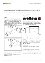
4. DEFROST FUNCTION (THERMO ICE)
During cold periods when frost appears, the defrost function
takes care of defrosting and the supply air fan stops.
The defrost function does not start until it´s needed, which means
when a major part of the counterflow heat exchanger is covered
with frost. This function keeps the heat recovery as high as pos-
sible in each moment. The defrost function makes a difference by
frost and condence. The defrost cycle works for 15 minutes.
Содержание eCO Premium
Страница 1: ...INSTALLATION AND MAINTENANCE MANUAL eCO PREMIUM...
Страница 47: ......


