eCO Premium™ - Installation & Maintenance
29
FläktGroup DC_9604GB_20190327_R6
Specifications are subject to alteration without notice
CONTROL FUNCTIONS (CONT.)
5. COOLING RECOVERY
Cooling recovery is activated if the outdoor temperature is 2° C
higher than the extract air temperature and the unit is operating
in “summer mode”, and the bypass damper will close.
6. NIGHT COOLING
Night cooling is used in summertime to reduce cooling load
at unit start-up and to limit the maximum temperature during
non-working hours. This is done by making use of cold outside air
during cool summer nights.
6.1. STARTING CONDITIONS
a. Night cooling activated
b. Auto mode enabled
c. The unit is in the stop position as scheduled
6.2. TEST PERIOD AND EVALUATION
a. The unit is started at. 22.00 and then operates at
normal speed
b. At 22.15 it is determined whether night cooling is needed or
not. The following conditions must be met:
1. The unit is in “Summer mode” .
2.Outdoor temperature < Extract temperature – Delta.
3. Extract temperature > Room se Hysteresis.
c. If the above conditions are met the night cooling starts.
6.3. THE FOLLOWING TAKE PLACE DURING NIGHT COOLING
a. Bypass damper will open, post heater and any cooling is
blocked.
b. The fans are switched to the high speed setting.
6.4. NIGHT COOLING TAKES PLACE AS LONG AS THE
FOLLOWING CONDITIONS ARE FULFILLED:
a. Unit is in “Summer mode”.
b. Outdoor temperature < Extract temperature
–
Delta.
c. Extract temperature > Room setpoint.
d. Function’s maximum activation time is not reached.
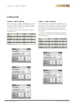
Parameters
Value (exemple) Comment
Night cooling activated
Yes
Activated night cooling
Room setpoint
22°C
Room setpoint night cooling
Delta
5°C
Min difference room temp.
Hysteresis
2°C
Hysteresis for night cooling
Test time, start
kl. 22.00
Start time for night cooling test
Test time, off
kl. 22.15
Stop time for night cooling test
Max time
540 minutes
Maximal activation time
for night cooling
7. PRESSURE OR FLOW CONTROL
PRESSURE CONTROL (COP (ACCESSORY))
Control principle in which the unit maintains a constant duct
pressure. Normally used in variable flow systems (VAV).
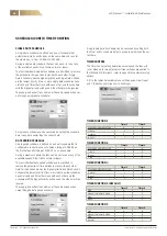
Size
1
2
3
4
5
6
k-value extract air fan 123.2
80.3
59.5
44.4
29.1
28.8
k-value supply air fan 123.2
80.3
59.5
44.4
29.1
28.8
4-20mA
LED
Jumper 1
Jumper 2
Jumper 3 24VDC
GND
0-10V
LED
Jumper 1
Jumper
2
Jumper
3
push-button
Pressure sensor is supplied as a loose accessory. Pressure
control regulates air pressure in index duct (duct with a maxi-
mum pressure drop, and where the static pressure is lowest).
The pressure sensor (GP3) is placed at the beginning of this duct.
The extract sensor (GP4) is placed in the extract duct at a suit-
able location with representative pressure. For settings see the
Parameter list.
CONSTANT FLOW CONTROL (CAV)
Control principle in which the unit maintains a constant duct
flow. Using a measurement pressure
D
p
m
in Pa and a constant
k, the airflow q in l/s is calculated with the follo wing formula:
q
= 1000
k
D
p
m
x
The measuring pressure,
D
p
m
, is the difference between the
pressure in the empty section at the fan inlet and the pressure
inside the inlet cone.
The pressure sensor is connected via two externally placed
measuring nipples. Value of the constant (k) is shown in the table
below. For settings see the parameter list.
ZERO POINT-CALIBRATION
CONNECTION OF PRESSURE SENSORS
The pressure sensor shall be set to the working range of 0–500 Pa.
Location
Terminal Connection
No. Pressure sensor
Supply air duct
GP3
Y
31
0–10 V
G0
30
GND
G
29
24 V DC
Extract air duct
GP4
Y
45
0–10 V
G0
44
GND
G
43
24 V DC
The sensors must be zeroed during commissioning. They should
then be zeroed annually. The sensors should have been energi-
zed for approximately one hour before calibration is carried out.
After that, remove the hoses from the sensors. To start calibration
press the push-button next to the pressure range jumpers. The
red LED lights up and goes out after about a second. Reassemble
the air hoses. Done!
Содержание eCO Premium
Страница 1: ...INSTALLATION AND MAINTENANCE MANUAL eCO PREMIUM...
Страница 47: ......

