55
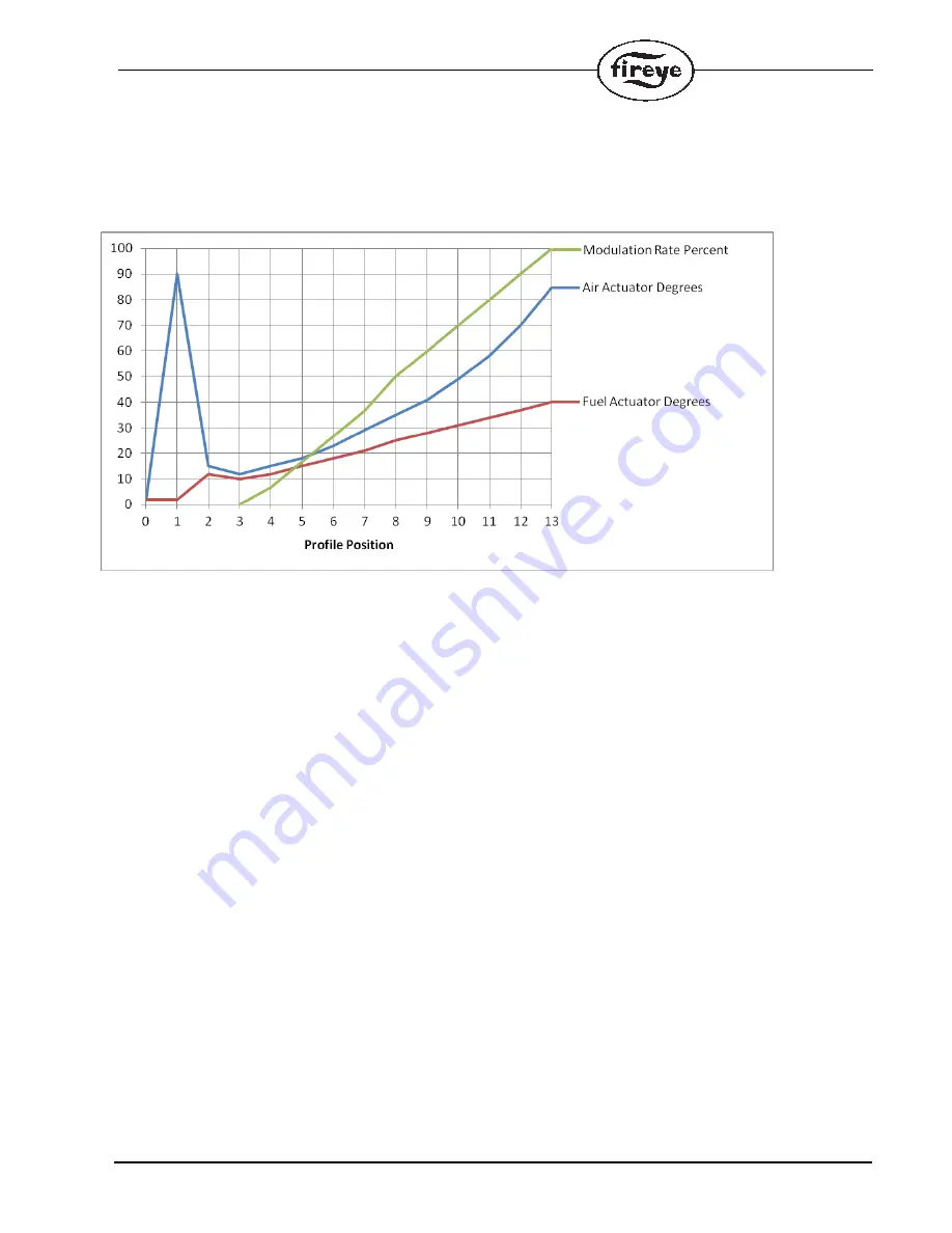
Graph 2 shows the same commissioned actuator positions for both the AIR and FUEL servos as
shown graph 1 but with the FUEL actuator used as the master because a VFD is used. Notice how
different the modulation curve appears. Because the FUEL's p03 position is 10 degrees and the p13
position is 40 degrees, the 50% position occurs at ((40-10) X 50%) + 10 = 25 degrees. This puts the
50% modulation rate close to the p8 position where the AIR servo is close to 35 degrees.
Graph 2 (VFD used):
The reason for the difference between the two example curves is due to the AIR servo's upward curv-
ing slope but the FUEL servo's slope is straight. The modulation rate curve will resemble the curve
of master servo.
Selecting manual or automatic modulation rate:
To adjust the modulation rate, the user must first put the PPC4000 into the manual modulation mode.
This is done by pressing the AUTO MAN button or by enabling this function through a digital input.
Once the manual modulation rate is selected, the display will change from "MODULATION RATE"
to "MANUAL MOD RATE".


