20
SERVO MOTOR SETUP AND WIRING
The PPC4000 must have a “master servo” in order to generate a valid modulation curve. In a typical
setup, without VFD, the AIR servo is selected as the master servo; if a VFD is used, the first fuel
servo is then selected as the master servo. The modulation rate, low fire to high fire, and therefore the
servo(s) positions are derived from the master servo commissioning values. Each servo is equipped
with an internal rotary switch that is used to select its communication address. The address range is 1
to 10. It does not matter what each servo address is but it is required that each servo have its own
unique
address.
The servo addresses are learned during power on
.
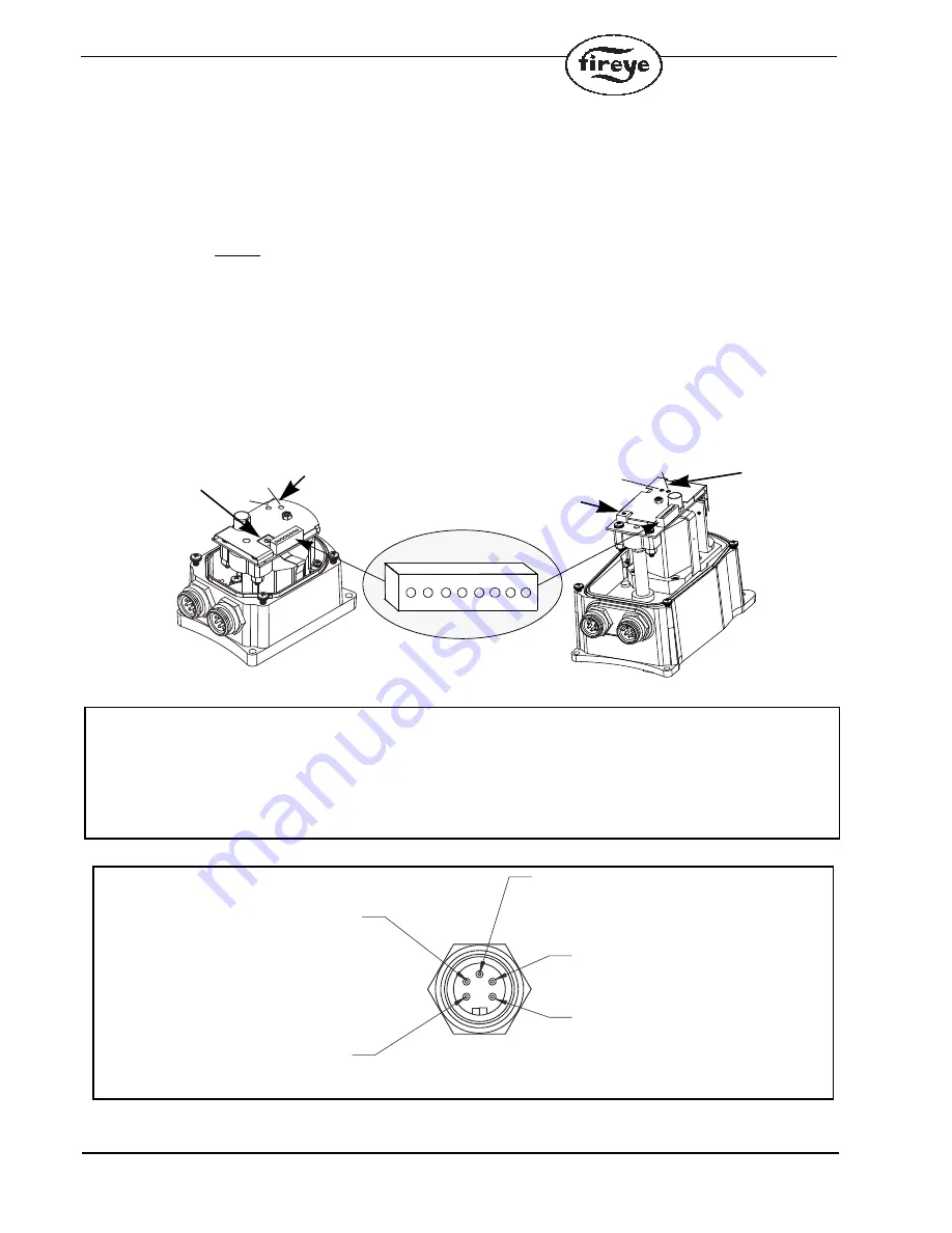
It is recommended that servos be wired to the PPC4000 in a multi-drop configuration. That is,
cabling traverses from the control to the first servo, to the second servo, to the third servo, etc. Servo
types FX04-1, FX20-1 and FX50-1 are pre-wired to connectors located on the body of the servo.
Cordsets having female connectors on both ends are available in 6 and 40 foot lengths. Field wire-
able connectors and cable are also available. See ORDERING INFORMATION for part numbers.
Servo types FX04, FX20 and FX50 allow the installation of conduit fittings and the user to wire
directly to the servos using the terminal strips located inside the servo. Always connect the ground
first to eliminate any ESD (electro-static discharge) potential.
.
Servo
Wiring Diagram, internal
Refer to bulletins NEX-3004, NEX-3020 and NEX-3050 for operational details, setting the
addresses and servo movement.
FX04-1
UNIT ADDRESS
MANUAL MOVEMENT
FX20-1
UNIT
ADDRESS
MANUAL
MOVEMENT
CCW
CCW
CW
CW
1
1
4
4
2 2 5 5
WARNING
-
DO
NOT
USE
THE
MANUAL
MOVEMENT
SWITCHES
ON
THE
SERVO
MOTORS
DURING
AUTOMATIC
OPERATION
OR
THE
FIRING
CYCLE
OF
THE
BURNER.
USE
OF
THE
MANUAL
MOVEMENT
SWITCHES
OPERATES
THE
SERVOMOTORS
INDEPENDENT
OF
THE
PPC4000
CONTROL
AND
COULD
RESULT
IN
AN
OFF-RATIO
CONDITION
IF
OPERATED
DURING
AUTOMATIC
OPERATION
OR
THE
FIRING
CYCLE
PIN 1 BLACK
RS-485 B(-)
PIN 2 BLUE
24 VDC RETURN
PIN 3 GREEN/YELLOW
EARTH GROUND
PIN 4 BROWN
RS-485 A(+)
PIN 5 WHITE
24 VDC SUPPLY
To P12.5
To P2.4, P2.5 or P2.6
To P12.6
To P2.2 or P2.3


