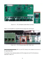
Figure 3.3.2 shows a photograph of 2 FCU circuit boards with all ancillary connection
cables (although no audio wires and no faders) fitted.
NOTE: As the ‘daisychain’ power and data cables are used to allow all FCU boards
to connect to the MCU through a single set of connectors/cables, they are only
necessary for systems which include more than 1 FCU.
Figure 3.3.2 – FCU Boards With FaderMate System Connections
The standard motorised fader (including connector) adds a further 3.5cm to the required
fader tray depth giving a total required height of 6 cm from the bottom of the fader
faceplates to the bottom of the fader tray.
To illustrate the space taken up by an FCU underneath the motorised faders. Figure 3.3.3
shows a single motorised fader installed in a console above an FCU which has been fitted
in the fader tray.
12
Содержание Master Control Unit
Страница 1: ...Product Fitting Guide v1 0 0 October 2018 2018 FaderMate All rights reserved 1...
Страница 11: ...Figure 3 3 1 FCU Circuit Board Dimensions 11...
Страница 23: ...Figure 4 4 4 Data Connections 23...
Страница 26: ...Figure 4 5 4 Daisychain Power Connections Block Diagram 26...
Страница 36: ...Version History Version Date Author Details 1 0 0 08 October 2018 AJN First release 36...


