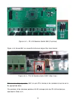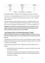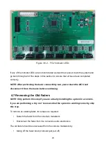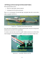
Please observe the following points when making the power connections:
•
All power connections should be made using an appropriate length of the supplied
two core (brown/blue) power wire
•
The 0V terminal of the MCU must be connected to to the ‘-’ terminal of
CON2
on a
single FCU using the blue wire in the two core pair.
•
The 12V terminal of the MCU must be connected to the ‘+’ terminal of
CON2
on the
same FCU using the brown wire in the two core pair.
•
The wires should enter the rear of the FCU power connector.
Figure 4.5.3 shows connections at both ends of the MCU → FCU power distribution
arrangement.
Figure 4.5.3 – Power Connections – MCU and FCU 1
Each remaining FCU must then be supplied with power by connecting its
CON2
terminals
to the
CON3
terminals of the previous FCU in the ‘chain’ using appropriate lengths of the
supplied wire.
For example, the connections required for a 24 channel installation are shown in Figure
4.5.4.
25
Содержание Master Control Unit
Страница 1: ...Product Fitting Guide v1 0 0 October 2018 2018 FaderMate All rights reserved 1...
Страница 11: ...Figure 3 3 1 FCU Circuit Board Dimensions 11...
Страница 23: ...Figure 4 4 4 Data Connections 23...
Страница 26: ...Figure 4 5 4 Daisychain Power Connections Block Diagram 26...
Страница 36: ...Version History Version Date Author Details 1 0 0 08 October 2018 AJN First release 36...


