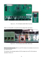
Figure 4.2.1 – FCU ID Selection Switch SW1 (Top View)
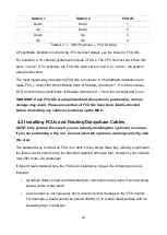
Figure 4.2.2 shows
SW1
as viewed from the rear edge of the circuit board.
Figure 4.2.2 – FCU ID Selection Switch SW1 (Rear View)
Prior to connecting any cables,
SW1
on each FCU module in the installation must be set to
the appropriate state.
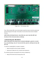
The positions of the individual switches in SW1 correspond to the FCU ID numbers as
described in Table 4.2.1.
19
Содержание Master Control Unit
Страница 1: ...Product Fitting Guide v1 0 0 October 2018 2018 FaderMate All rights reserved 1...
Страница 11: ...Figure 3 3 1 FCU Circuit Board Dimensions 11...
Страница 23: ...Figure 4 4 4 Data Connections 23...
Страница 26: ...Figure 4 5 4 Daisychain Power Connections Block Diagram 26...
Страница 36: ...Version History Version Date Author Details 1 0 0 08 October 2018 AJN First release 36...


