manualshive.com logo in svg
background image

13

ENGLISH

During these 5 seconds, in order to lighten the load on the 

release system, you can send OPEN pulses within a time interval 

of 2 seconds from each other, in order to reverse the carriage. 

One pulse corresponds to a 5 millimetre travel.

N.B.: The carriage can be seen reversing only during normal 

operation of the automated system. 

The control unit establishes the deceleration points.

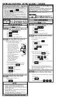
MANUAL LEARNING WITH LOGIC “E” (SEMI-AUTOMATIC)

Press the SET UP push-button for one second. The SET UP LED starts 

to flash when you release the push-button. Start the following 

procedure within 8 seconds (otherwise the operator will perform 

automatic learning): 

1)  Give the 1st OPEN command: the operator performs a

     slowed-down closing manoeuvre until it detects the stop

       point and stops.

2)   Give the 2nd OPEN command: the operator continues with

      an opening movement.

3)   Give the 3rd OPEN command in order to define the point

       where you wish deceleration to begin.

4)   Give the 4th OPEN command to define the opening stop

       point, or wait for the automated system to detect arrival at

      the stop point and then stop. 

5)   Give the 5th OPEN command: the automated system begins

      the closing movement.

6)   Give the 6th OPEN command in order to define the point

       where you wish deceleration to begin.

7)   Wait for the door to reach the stop point and for the 

       operator to stop.

If the learning procedure terminated positively, the SET UP LED 

stops flashing and stays lighted for 5 seconds.

During these 5 seconds, in order to lighten the load on the

release system, you can send OPEN pulses within a time interval 

of 2 seconds from each other, in order to reverse the carriage. 

One pulse corresponds to a 5 millimetre travel.

N.B.: The carriage can be seen reversing only during normal 

operation of the automated system.  

AUTOMATIC LEARNING WITH LOGIC “A” (AUTOMATIC)

Hold down the SET UP push-button until the SET UP LED goes 

on (about 5 seconds). The SET UP LED starts to flash when you 

release the push-button.

1)   After 4 seconds the operator automatically closes the door

      by deceleration until the stop point is detected.

2)  The operator moves the door to open. Wait until the stop

        point is reached, or give an OPEN command in the position

      where you wish to stop motion.

3)   The operator closes the door.

4)   Wait for the door to reach the stop point and for the 

       operator to stop.

If the learning procedure terminated positively, the SET UP LED 

stops flashing and stays lighted for 5 seconds.

During these 5 seconds, in order to lighten the load on the 

release system, you can send OPEN pulses within a time interval 

of 2 seconds from each other, in order to reverse the carriage. 

One pulse corresponds to a 5 millimetre travel.

N.B.: The carriage can be seen reversing only during normal 

operation of the automated system. 

The control unit establishes the deceleration points.

Pause time is fixed at 3 minutes.

MANUAL LEARNING WITH LOGIC “A” (AUTOMATIC)

Hold down the SETUP push-button until the SET UP LED goes 

on (about 5 seconds). The SET UP LED starts to flash when you 

release the push-button. Start the following procedure within 

4 seconds (otherwise the operator will perform automatic SET 

UP).

1)  Give the 1st OPEN command: the operator performs a 

     deceleration closing manoeuvre until it detects the stop

       point.

2)   Give the 2nd OPEN command: the operator continues with

      an opening movement.

3)  Give the 3rd OPEN command in order to define the point

      where you wish deceleration to begin.

4)  Give the 4th OPEN command to define the opening stop

       point, or wait for the automated system to detect arrival at

        the stop point. After the stop, the time when the automated

         system is left open starts to be counted . This will be the pause

    time which will be observed during manual operation (3 

      minutes maximum).

5)    Give the 5th OPEN command: the pause time count is stopped 

      and the closing movement starts.

6)  Give the 6th OPEN command in order to define the point

      where you wish deceleration to begin.

7)   Wait for the door to reach the stop point and for the 

      operator to stop.

If the learning procedure terminated positively, the SET UP LED 

stops flashing and stays lighted for 5 seconds. 

During these 5 seconds, in order to lighten the load on the 

release system, you can send OPEN pulses within a time interval 

of 2 seconds from each other, in order to reverse the carriage. 

One pulse corresponds to a 5 millimetre travel.

N.B.: The carriage can be seen reversing only during normal 

operation of the automated system. 

ON GROUND MANUAL SETTING OF STOP CONTACT POINT (at the 

learning stage)

During the learning stage, the operator searches for the 

on-ground stop point, using the maximum force that can be 

supplied (600N). To prevent excessive stress, the stop point can 

be determined also manually: when the automated system 

performs the closing movements, give an OPEN command 

when the stop point is reached. If the stop commands at first and 

second closing were inconsistent, the automated system signals 

the fault status and the learning cycle must be repeated.

During normal operation, the automated system in any case 

searches for the stop contact point, but it exercises only the 

force necessary to move the door. 

When the learning cycle has finished, make the automated 

system perform a complete cycle, in order to acquire 

the correct closing stop point. If, after the end of this 

cycle, the automated system opens the door again, 

command closure.

11.3 Pre-flashing

The pre-flashing function can be enabled and disabled 
(following an OPEN command, the unit activates the flashing
lamp for 5 seconds before it starts the movement). 
Procedure:
1)  Press and hold down the SET UP push-button.
2)  Press the OPEN push-button too after about 3 seconds. If the 

SET UP LED goes ON, pre-flashing was activated, if instead, 

it stays OFF, pre-flashing was disabled.

3)  Release both push-buttons.

Содержание E600

Страница 1: ...00 board components p 10 8 3 Terminal boards and connectors p 10 8 4 DS1 Programming dip switches p 10 8 5 Operating logics p 10 9 COURTESY LIGHT p 11 10 CONNECTIONS p 11 11 PROGRAMMING p 12 11 1 Sett...

Страница 2: ...cm install the external control devices at a height of not below 150cm clear of the door movement area but in a position enabling visual control of the area When you have finished installing we advise...

Страница 3: ...ing 16 Use of at least one indicator light e g FAACLIGHT is recommended for every system as well as a warning sign adequately secured to the frame structure in addition to the devices mentioned at poi...

Страница 4: ...access Do not use them for any other purpose 1 DIMENSIONS 2 TECHNICAL SPECIFICATIONS AUTOMATED SYSTEM D600 3 ANCILLARY ELECTRICAL EQUIPMENT Prepare the electric system in keeping with the instructions...

Страница 5: ...oducts but do not use grease and in any event follow the manufacturer s instructions Check correct balance and if the opening mechanical stops have been installed Remove the door s existing closing me...

Страница 6: ...g guide until it is near the front terminal the one opposite the drive coupling 3 Assemble the front fitting Fig 7 ref B to the transmission unit Fig 7 ref A 4 Apply slight tension to the chain tighte...

Страница 7: ...corresponding to the maximum height reached by the door during movement see Fig 4 3 Position the securing bracket of the front fitting so that the lower edge is at least 5 mm above the intersection po...

Страница 8: ...5 Mark drill and secure the fitting to the door using the screws ref Fig 17 NOT supplied Fig 14 Fig 15 Fig 18 Fig 17 Fig 16 8 Lift the sliding guide until the rear fitting is at the same level as the...

Страница 9: ...off the ground and cut off the excess section of rope 2 Make a knot at the end of the rope and assemble the release handle Fig 22 3 Pull the release handle down and check if the door can be moved man...

Страница 10: ...lse Stop Fsw CLOSED Opens No effect 2 No effect OPENING Locks Locks 2 No effect 1 OPEN Closes No effect 2 No effect 1 CLOSING Reverses motion Locks 2 Reverses motion LOCKED Closes No effect 2 No effec...

Страница 11: ...27 If the STOP input is not used jumper connect the input to the terminal If the photocells are not used connect the FSW input to terminal TX FSW Input status LEDS The automated system stopped and at...

Страница 12: ...However in automatic mode the unit independently determines the movement parameters If the procedure is not correctly concluded e g due to excessive friction during door movement the unit signals a fa...

Страница 13: ...establishes the deceleration points Pause time is fixed at 3 minutes MANUAL LEARNING WITH LOGIC A AUTOMATIC Hold down the SETUP push button until the SET UP LED goes on about 5 seconds The SET UP LED...

Страница 14: ...ref 5 The relevant LED starts to flash slowly for 5 sec 6 Within these 5 sec while the radio control LED is still flashing press and hold down the required push button on the radio control the radio c...

Страница 15: ...ush button flashes for the first 5 sec and then flashes more quickly for the next 5 sec 3 Both LEDs light up on steady beam for 2 sec and then go OFF 4 Release the pressed push button when both LEDs l...

Страница 16: ...ntly separating it from the plastic housing Unscrew the 4 screws in the 4 corners of the plastic housing Separate it from the base House the control unit as shown in Fig 36 First hook on the two faste...

Страница 17: ...before the manoeuvre is started Learning is not finished correctly and the SET UP LED flashes to signal a fault The automated system frequently reverses motion during the opening and or closing manoeu...

Страница 18: ...ns of a transmission chain or belt pulls the door open to allow access If the automatic mode was set the door closes automatically after pause time has elapsed An opening pulse given during the openin...

Страница 19: ...chnician Customer 9 Technician Customer 10 Technician Customer Installer Customer Type of system Serial No Installation date Start up PART MODEL SERIAL NUMBER Operator Safety device 1 Safety device 2...

Страница 20: ...D600 D600...

Страница 21: ......

Страница 22: ...orre dare un nuovo impulso di apertura Se viene rilevato un ostacolo in chiusura nella stessa posizione per tre volte consecutive l automazione assume tale quota come nuova battuta di chiusura e si po...

Страница 23: ...oppia fotocellule 2 Dispositivo di comando 1 Dispositivo di comando 2 Radiocomando Lampeggiante Nr Data Descrizione intervento Firme 1 Tecnico Cliente 2 Tecnico Cliente 3 Tecnico Cliente 4 Tecnico Cli...

Страница 24: ...ns of a transmission chain or belt pulls the door open to allow access If the automatic mode was set the door closes automatically after pause time has elapsed An opening pulse given during the openin...

Страница 25: ...chnician Customer 9 Technician Customer 10 Technician Customer Installer Customer Type of system Serial No Installation date Start up PART MODEL SERIAL NUMBER Operator Safety device 1 Safety device 2...

Страница 26: ...e moteur lectrique qui par l interm diaire de la transmission cha ne ou courroie entra ne la porte en position d ouverture et permet l acc s Si l on a s lectionn le fonctionnement automatique la porte...

Страница 27: ...nicien Client Installateur Client Type d installation N de s rie Date d installation Activation COMPOSANT MOD LE N DE SERIE Op rateur Dispositif de s curit 1 Dispositif de s curit 2 Paire de photocell...

Страница 28: ...1 wird der Elektromotor in Betrieb gesetzt der das Tor ber einen Ketten oder Riemenantrieb ffnet und Zugang Zufahrt erm glicht Wenn der Automatikbetrieb eingestellt wurde schlie t sich das Tor selbstt...

Страница 29: ...hniker Kunde 10 Techniker Kunde Monteur Kunde Art der Anlage Seriennummer Installationsdatum Inbetriebnahme BAUTEIL MODELL SERIENNUMMER Antrieb Sicherheitsvorrichtung 1 Sicherheitsvorrichtung 2 Fotoze...

Страница 30: ...impulso para obtener el cierre Un impulso de apertura durante la fase de apertura detiene el movimiento Un impulso de apertura durante la fase de cierre causa siempre la inversi n del movimiento Un i...

Страница 31: ...e 10 T cnico Cliente Instalador Cliente Tipo de equipo N de serie Fecha de instalaci n Activaci n COMPONENTE MODELO N DE SERIE Operador Dispositivo de seguridad 1 Dispositivo de seguridad 2 Par de fot...

Страница 32: ...ekt en toegang mogelijk maakt Als de automatische werking is ingesteld sluit de deur vervolgens uit zichzelf na de pauzetijd Als tijdens de openingsfase een openingsimpuls wordt gegeven heeft dit geen...

Страница 33: ...0 Technicus Klant Installateur Klant Type installatie Serienummer Datum installatie Activering ONDERDEEL MODEL SERIENUMMER Aandrijving Veiligheidsvoorziening 1 Veiligheidsvoorziening 2 Paar fotocellen...

Страница 34: ......

Страница 35: ...n in vorliegendem Handbuch sind unverbindlich FAAC beh lt sich das Recht vor ohne die wesentlichen Eigenschaften dieses Ger tes zu ver ndern und ohne Verbindlichkeiten in Bezug auf die Neufassung der...

Отзывы: