3GS Technical Manual
Issue 4.5 August 2005
8-82 Programming Menus
A
REA
S
ETUP
Function:
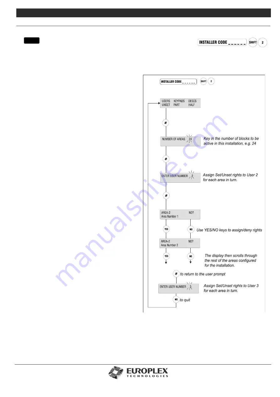
The Area Setup menu allows you to set the number of areas to be active in the system and assigns Area Set/Arm
and Unset/Disarm rights to system users, keypads to areas, and programming area names.
Additional Information
The system currently allows for up to 30 areas, and can be
set/armed for any number of areas up to 30.
Setting the number of areas in the system is an installer
option
only
. The option to assign user rights to areas is
available to both Installer and Master User.
Providing the user with an area gives them the right to set/
arm or unset/disarm that area. However, the user must also
be given the PART SET user option for area set/arm, and the
HALF SET user option for area set/arm – see the
3GS
Version 5 User Guide
. This allows the user to be given or
denied the right to set/arm an area. Installer’s are not
allowed to set/arm or unset/disarm areas.
Once the user set/arm or unset/disarm rights have been
assigned, they are effective immediately so that individual
users will only be able to set/arm or unset/disarm those
areas to which they have rights. PART and HALF keys are
used for Area Unset/Disarm and Area Setting/Arming – see
the
3GS Version 5 User Guide
. Setting the number of areas
to 0 will configure the system for no areas and PART and
HALF keys are used to PART SET and HALF SET the system.
Area Keypads
Use this option to assign keypads to areas so that messages
for individual areas can only be seen on the keypads
assigned to the area.
The system may be set up so that each area has a keypad
installed at a point convenient to the Exit/Entry route. In this
case, you should assign this keypad to the area. Once
assigned, the keypad will display only those alert messages
relating to that particular area, and when the user is setting
the system, will display the number of that area first
allowing instant setting.
Alternatively, one keypad may be positioned at a point
central to a number of areas – for example, Areas 5 and 7.
In this case, the keypad can be assigned to both areas and
will then display messages for these two areas only. When
setting, the display will prompt the user to first set/arm Area
5, followed by Area 7, and will then scroll through the other
areas configured.
menu
Содержание 3GS
Страница 4: ...Introduction iv...
Страница 12: ...Introduction 8...
Страница 14: ...1...
Страница 18: ...System Overview 1 6...
Страница 20: ......
Страница 22: ...Hardware Overview 2 4 SYSTEM CONFIGURATION The following diagram shows a typical configuration of the system...
Страница 26: ......
Страница 34: ......
Страница 38: ...Intelligent PSUs 4 6...
Страница 40: ......
Страница 97: ...Issue 4 5 August 2005 Nodes 5 59...
Страница 98: ...Issue 4 5 August 2005 Nodes 5 61...
Страница 100: ......
Страница 106: ...3GS Technical Manual...
Страница 116: ...3GS Technical Manual 7 12 Programming Overview Issue 4 5 August 2005 3GS Initial Setup Menu...
Страница 118: ...3GS Technical Manual...
Страница 146: ...3GS Technical Manual Issue 4 5 August 2005 Programming Menus 8 31 Node Configure Inputs Menu...
Страница 153: ...3GS Technical Manual Issue 4 5 August 2005 8 38 Programming Menus Service Mode Test Menu...
Страница 155: ...3GS Technical Manual Issue 4 5 August 2005 8 40 Programming Menus Service Mode Monitor Menu...
Страница 217: ...3GS Technical Manual Issue 4 5 August 2005 8 108 Programming Menus...
Страница 218: ...3GS Technical Manual Issue 4 5 August 2005 Programming Menus 8 109...
Страница 220: ......
Страница 222: ...3GS Version 5 User Guide 9 5 3GS SYSTEM KEYPAD DISPLAY...
Страница 254: ...3GS Version 5 User Guide 9 37 Some examples of Alert Messages...
Страница 262: ...3GS Version 5 User Guide 9 45 User name max 24 characters User no 17 18 19 20 21 22 23 24 25 26 27 28 29 30 31 32...
Страница 264: ......
Страница 265: ...I n t h i s c h a p t e r HHT Overview 10 3 Main Menu 10 5 HAND HELD TERMINAL HHT 10...
Страница 266: ......
Страница 280: ......
Страница 288: ......
Страница 290: ......
Страница 293: ...Issue 4 5 August 2005 DM1200 Digital Communicator Modem 12 5...
Страница 301: ...I n t h i s c h a p t e r Network Router Overview 13 3 Sample Connection Diagram Scenarios 13 4 NETWORK ROUTER 13...
Страница 302: ......
Страница 304: ...Network Router 13 4 SAMPLE CONNECTION DIAGRAM SCENARIOS...
Страница 308: ...Network Router 13 8...
Страница 310: ......
Страница 316: ...IntelliBell 14 8 SELF ACTIVATING BELL To connect a Self Activating Bell SAB to the 3GS system see the following diagram...
Страница 318: ......
Страница 338: ...Issue 4 5 August 2005 Technical Specifications 15 23...
Страница 339: ...I n t h i s c h a p t e r 3GS Overview 16 5 Installing 3GS 16 6 Installing the Dongle 16 7 Upgrading 16 8 16 PC SOFTWARE...
Страница 340: ...1...
Страница 346: ......
Страница 366: ...17 22...
Страница 367: ...I n t h i s c h a p t e r Introduction to CiTeC II 18 3 CITEC II INSTALLATION 18...
Страница 368: ......
Страница 370: ...CiTeC II Installation 18 4...
Страница 377: ...Issue 4 5 August 2005 19 7...
Страница 378: ...19 8...
Страница 385: ......
Страница 386: ......


