background image

Adjustment

Rev. A

4-3

4.1.2 Adjustment 

Tools

Table 4-2 shows the tools necessary to adjust this printer and the menus to be adjusted.

Tools for adjusting

Item to be adjusted

Program disk for adjustment
  

y

 DOS system


y

 GWBASIC


y

 Adjustment program

   (Version J70C00E)

‰

 Customer data writing operation

‰

 Initial ink charge (Ink charge)

‰

 Head voltage adjustment

‰

 Head angular adjustment

‰

 Black/color head vertical adjustment

‰

 Head gap adjustment

‰

 Bi-d adjustment

Thickness gauge (1.1 mm)

‰

Platen gap adjustment

The program disk for adjustment consists of the total of 40 files such as DOS system, GWBASIC.EXE,
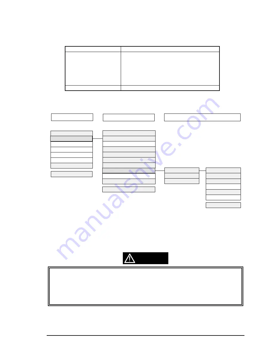
and adjusting programs. The adjusting menus in the program are as shown below:

Select the item in the light gray shaded box to perform necessary adjustment. You can proceed to the sub
menu thorough the item in the dark gray shaded box in the bold line. Selecting “All adjustment” in the
sub menu enables you to perform the following adjustments consecutively;“ Head angular adjustment”,
“BK.-M Linear adjustment” and “Head GAP adjustment/Bi-d adjustment” This section, however, only
refers to the individual adjustment methods.

;

During adjustment, values such as Customer data, head voltage value, head gap adjustment
value, and Bi-d adjustment value are written into the EEPROM at the specified timing as follows;

„

 Customer data

:

At performing “Print Inspection”.

„

 Head voltage value

:

When the “Return” key is pressed after entering the 
values during “Write to the Head voltage value” 
menu . The data is then transferred to the printer.

„

 Bi-d/ Head gap adjustment value:

At performing “Print Inspection”.

Table 4- 2. Adjustment Tools

Input of Customer data

Adjustment/Print inspection
Change of center value
Input of comment
Change of date
Change of time
End

Select Menu :?_

Ink charge
Write to the Head voltage value
All adjustment
Head angular adjustment
BK.-M Linear adjustment
Head GAP timing adjustment
Bi-d adjustment
Print inspection
Ink discharge
Customer data change/End

Input M/C No. : ?_
Black voltage value :
Color voltage value :

GOS paper print test
S.F. paper print test
O.Q.A print  test
Cleaning
Return to the MENU
Letter paper print test

Select Menu :?_

Select Menu :?_

Main menu

Sub menu

Print inspection sub menu

Figure 4-1. Adjustment Program Menu

CAUTION

Содержание Stylus Color 800

Страница 1: ...EPSON COLOR INK JET PRINTER EPSON Stylus COLOR 800 SERVICE MANUAL SEIKO EPSON CORPORATION 4007371 ...

Страница 2: ...al However should any errors be detected SEIKO EPSON would greatly appreciate being informed of them The above notwithstanding SEIKO EPSON can assume no responsibility for any errors in this manual or the consequences thereof EPSON is a registered trademark of SEIKO EPSON CORPORATION General Notice Other product names used herein are for identification purposes only and may be trademarks or regist...

Страница 3: ...ANUAL DO NOT CONNECT THE UNIT TO A POWER SOURCE UNTIL INSTRUCTED TO DO SO WHEN THE POWER SUPPLY CABLE MUST BE CONNECTED USE EXTREME CAUTION IN WORKING ON POWER SUPPLY AND OTHER ELECTRONIC COMPONENTS CAUTION 1 REPAIRS ON EPSON PRODUCT SHOULD BE PERFORMED ONLY BY EPSON CERTIFIED REPAIR TECHNICIAN 2 MAKE CERTAIN THAT THE SOURCE VOLTAGE IS THE SAME AS THE RATED VOLTAGE LISTED ON THE SERIAL NUMBER RATI...

Страница 4: ...omponents of the printer CHAPTER 2 OPERATING PRINCIPLES Describes the theory of printer operation CHAPTER 3 DISASSEMBLY AND ASSEMBLY Includes a step by step guide for product disassembly and assembly CHAPTER 4 ADJUSTMENT Includes a step by step guide for adjustment CHAPTER 5 TROUBLESHOOTING Provides EPSON approved techniques for troubleshooting CHAPTER 6 MAINTENANCE Describes preventive maintenanc...

Страница 5: ...sue The following chapters have been revised Chapter 1 Pages l l 1 2 l 6 Chapter 2 Pages 2 l 4 2 20 2 23 Chapter 3 Page 3 l 0 Chapter 4 Pages 4 2 through to 4 25 The following chapters have been revised Chapter 2 Pages 2 8 2 l 6 Chapter 5 Pages 5 8 through to 5 l 2 5 l 8 The following chapter has been revised Chapter 2 Pages 2 20 V ...

Страница 6: ...vi TABLE OF CONTENTS CHAPTER 1 GENERAL DESCRIPTION CHAPTER 2 OPERATING PRINCIPLES CHAPTER 3 DISASSEMBLY AND ASSEMBLY CHAPTER 4 ADJUSTMENT CHAPTER 5 TROUBLESHOOTING CHAPTER 6 MAINTENANCE APPENDIX ...

Страница 7: ...ons 1 9 1 3 14 Physical Specifications 1 9 1 4 Firmware Specifications 1 10 1 4 1 Control Codes and Character Specifications 1 10 1 4 2 Input Data Buffer 1 12 1 5 Interfaces 1 13 1 5 1 Parallel Interface Forward Channel 1 13 1 5 2 Parallel Interface Reverse Channel 1 16 1 5 3 Mac Serial Interface 1 17 1 5 4 Optional Interface 1 18 1 5 5 Preventing Hosts from Data Transfer Timeout 1 18 1 5 6 Interf...

Страница 8: ...1 7 Main Components 1 27 1 7 1 C202 MAIN Board 1 28 1 7 2 C202 PSB PSE Board 1 29 1 7 3 C202 Panel Board 1 30 1 7 4 Printer Mechanism 1 30 1 7 5 Housing 1 31 ...

Страница 9: ...lity and high capacity This printer holds 100 cut sheets 55 g m 2 10 envelopes 20 sheets of glossy paper 30 index cards 50 transparency film sheets 70 sheets of special paper 2 interfaces built in and 1 optional interface card Mac serial interface up to approximately 900K bps Bidirectional parallel interface IEEE 1284 level 1 device Optional Type B interface card 4 scalable fonts and 5 LQ fonts Sc...

Страница 10: ...ck ink cartridge S020089 Color ink cartridge S041059 EPSON 360 dpi ink jet paper A4 100 sheets S041025 200 sheets S041060 EPSON 360 dpi ink jet paper Letter 100 sheets S041061 EPSON photo quality Ink jet paper A4 100 sheets S041026 200 sheets S041062 EPSON photo quality ink jet paper Letter 100 sheets S041067 EPSON photo quality ink jet paper Legal 100 sheets S041054 EPSON photo quality ink jet ca...

Страница 11: ...able Area for Raster Graphics Mode Print Mode Printable Area Available Dots CR Speed 180 dpi x 180 dpi 8 27 inch 1488 26 7 ips 360 dpi x 360 dpi 8 27 inch 2976 20 ips 720 dpi x 720 dpi 8 27 inch 5952 20 ips 1440 dpi x 720 dpi 1 8 27 inch 5952 2 10 ips 1 Printing at 1440 x 720 dpi is available only using the Microweave driver 2 Can be printed by sending following command sequence 1 Set print speed ...

Страница 12: ...g m 2 24 lb Quality Exclusive paper bond paper PPC 1 3 4 2 Transparencies Glossy Paper Table 1 5 Transparency Size Size Width Length A4 210 mm 8 3 297 mm 11 7 Letter 216 mm 8 5 279 mm 11 0 Thickness 0 075 mm 0 003 to 0 085 mm 0 0033 Note Printing on transparencies is available only at normal temperatures 1 3 4 3 Envelopes Table 1 6 Envelope Size Size Width Length No 10 241 mm 9 1 2 104 mm 4 1 8 DL...

Страница 13: ...m 0 12 3 mm 0 12 14 mm 0 54 Letter 216 mm 8 5 279 mm 11 7 3 mm 0 12 9 mm 1 0 35 3 mm 0 12 14 mm 0 54 B5 182 mm 7 2 257 mm 10 1 3 mm 0 12 3 mm 0 12 3 mm 0 12 14 mm 0 54 Legal L 216 mm 8 5 536 mm 14 0 3 mm 0 12 9 mm 1 0 35 3 mm 0 12 14 mm 0 54 Statement 139 7 mm 5 5 215 9 mm 8 5 3 mm 0 12 3 mm 0 12 3 mm 0 12 14 mm 0 54 Executive 190 5 mm 7 5 254 mm 10 3 mm 0 12 3 mm 0 12 3 mm 0 12 14 mm 0 54 1 3 mm ...

Страница 14: ...EPSON photo quality paper 65 sheets EPSON 360 dpi paper 65 sheets EPSON photo quality glossy paper 20 sheets EPSON photo quality glossy film 30 sheets 1 2 EPSON ink jet transparencies 30 sheets 1 EPSON photo quality cards 30 sheets 2 EPSON photo quality self adhesive sheets 1 sheet 1 When 30 sheets are loaded in the ASF you must set the TOP margin to more than 30 mm Otherwise you must load the pap...

Страница 15: ...s expired 3 Ink freezes below 4 C 23 F however it will be usable again after keeping it for more than 3 hours at room temperature Color Ink Cartridge Table 1 12 Color Ink Cartridge Specifications Color Ink Cartridge Type Exclusive cartridge Color Magenta Cyan Yellow Quick Penetration Print Capacity 300 pages A4 at 360 dpi 5 duty each color Ink life 2 years from indicated production date Storage Te...

Страница 16: ...t 0 2 A Maximum 0 3A Power consumption Approximately 18 W ISO IEC 10561 Letter pattern Insulation resistance 10M ohms min between AC line and chassis 500 VDC Energy star complinat Dielectric strength 1 500 VAC rms for 1 minute between AC line and chassis 1 3 9 Reliability Total Print Volume 75 000 pages A4 Letter Printhead Life 2 000 million dots nozzle 1 3 10 Safety Approvals 120 V Version Safety...

Страница 17: ... 5 to 85 without condensation 2 Resistance to Vibration Operating 0 15 G 2 Non operating 0 50 G Resistance to Shock Operating 1 G within 1 ms 2 Non operating 2 G within 2 ms 1 Refer to the table above 2 In shipment container 1 3 14 Physical Specifications Weight 6 5 kg Dimensions 475 mm W x 274 mm D x 177 mm H 18 7 x 10 78 x 6 96 90 80 70 60 50 40 30 20 10 20 27 30 35 40 Temperature Humidity 80 H ...

Страница 18: ... 437 US Standard Europe PC 850 Multilingual PC 860 Portuguese PC 861 Icelandic PC 863 Canadian French PC 865 Nordic Abicomp BRASCII Roman 8 ISO Latin 1 NLSP version 19 character tables Italic table PC850 Multilingual PC 437 US Standard Europe PC 437 Greek PC 852 East Europe PC 853 Turkish PC 855 Cyrillic PC 857 Turkish PC 866 Russian PC 869 Greek MAZOWIA Poland Code MJK CSFR ISO 8559 7 Latin Greek...

Страница 19: ...12 cpi 15 cpi Scalable fonts EPSON Roman 10 5 pt 8 pt to 32 pt 2 pt increments EPSON Sans Serif 10 5 pt 8 pt to 32 pt 2 pt increments EPSON Roman T 10 5 pt 8 pt to 32 pt 2 pt increments EPSON Sans Serif H 10 5 pt 8 pt to 32 pt 2 pt increments Note Each typeface has 4 variations Normal Bold Italic and Bold Italic An example of variations for EPSON Roman is as follows EPSON Roman normal EPSON Roman ...

Страница 20: ...urope PC 850 Multilingual PC 860 Portuguese PC 861 Icelandic PC 863 Canadian French PC 865 Nordic BRASCII Abicomp Roman 8 ISO Latin 1 Supported Supported Supported NLSP Version Italic table PC 437 US Standard Europe PC 850 Multilingual Supported PC 437 Greek PC 852 East Europe PC 853 Turkish PC 855 Cyrillic PC 857 Turkish PC 866 Russian PC 869 Greek MAZOWIA Poland Code MJK CSFR ISO 8859 7 Latin Gr...

Страница 21: ...2 mA VOL 0 4 V CO 50 pF VIH 2 0 V VIL 0 8 V IIH 0 32 mA VIH 2 0 V IIL 12 mA VIL 0 8 V CI 60 pF Notes A LOW logic level on the Logic H signal line is as follows 2 0 V or less when the printer is powered off 3 0 V or more when the printer is powered on The receiver provides an impedance equivalent to 7 5K ohms to ground Adaptable Connector 57 30360 Amphenol or equivalent The BUSY signal is set HIGH ...

Страница 22: ...iming Forward Channel Table 1 15 Data Transmission Timing Parameter Minimum Maximum tsetup 500 ns thold 500 ns tstb 500 ns tready 0 tbusy 500 ns tt out 120 ns tt in 200 ns treply tack 500 ns 10 µs tnbusy 0 tnext 0 Note tt out shows the rise and fall time of every output signal tt in shows the rise and fall time of every input signal treply tack tnbusy tnext tstb tsetup thold data byte n data byte ...

Страница 23: ...at a HIGH level the printer is not ready to accept data 12 5 PE 28 O When this sign is at a HIGH level the paper empty status is detected 13 6 SLCT 28 O Always at HIGH level when the printer is powered on 14 7 AFXT 30 I Not used 31 8 INIT 30 I The falling edge of a negative pulse or a LOW signal on this line causes the printer to initialize Minimum 50 µs pulse is necessary 32 9 ERROR 29 O When the...

Страница 24: ...n Assignments and Signals Reverse Channel Pin No Signal Name Return GND Pin I O Description 1 HostClk 19 I Clock signal from the host computer 2 9 DATA 0 7 20 27 I These signals represent parallel data on bits 2 to 9 Each signal is HIGH when the data is logical 1 and LOW when the data is logical 0 10 PtrClk 28 O Clock signal from the printer 11 PtrBusy Data bits 3 7 29 O Busy signal from the print...

Страница 25: ...s Table 1 18 Connector Pin Assignments for Serial Interface Pin No Signal Name I O Functional Description 1 SCLK O Synchronous clock 2 CTS I Clear to send 3 TxD O Transmit data 4 S G I Signal ground 5 RxD I Receive data 6 TxD O Balanced transmit 7 DTR O Data terminal ready 8 RxD I Balanced receive Note Refer to the figure below for the connector pin arrangement Table 1 19 X ON X OFF DTR Protocol S...

Страница 26: ...cted manually or automatically Both modes are selected through default setting mode Manual Selection One of 3 interfaces selected through the default setting mode The selected interface is fixed Automatic Selection Automatic interface selection is enabled in default setting mode In automatic interface selection mode the printer is initialized to the idle state when it is powered on 1 scanning whic...

Страница 27: ...el Functions Buttons Functions Load Eject Loads or ejects paper Exits ink cartridge change mode 1 Cleaning Black Press for 2 seconds Performs black ink cartridge cleaning Enters ink cartridge change mode 2 Cleaning Color Press for 2 seconds Performs color ink cartridge cleaning Enters ink cartridge change mode 2 Cleaning Black Cleaning Color Press for 2 seconds Enters ink cartridge change mode In ...

Страница 28: ...ds Resets a specific area of EEPROM and Timer IC 2 1 means to press one button while holding down the other button s 2 Refer to Table 1 28 or the EEPROM map described in the Appendix LED Indicators Several printer conditions can be identified by LEDs on the control panel Which LED or LEDs lights varies depending on the condition See Table 1 24 for printer conditions and LED status Table 1 23 Print...

Страница 29: ...alic Italy Italic Spain 1 PC 437 PC 437 Greek PC 850 PC 853 PC 855 PC 852 PC 857 PC 866 PC 869 MOZOAWIA Code MJK ISO 8559 7 ISO Latin 1T Bulgaria PC 774 Estonia ISO 8859 2 PC 866 LAT Auto line feed On Off Network I F mode This mode is for network environment Off Used in usual environment On Used in network environment Loading position 3 mm 8 5 mm Others 3 Economy mode On Off Parallel I F transfer ...

Страница 30: ...See the flowchart below for the default setting method Hold down the Cleaning Color button and turn on the printer The printer prints 1 Firmwear version number The printer prints 1 The latest settings 2 Usage of this mode Change the settings NO YES NO Select the setting menu Cleaning Color button Change the setting value Load Eject button Memorize the new setting Cleaning Color button Start YES Tu...

Страница 31: ...Turn off the printer 1 6 4 Ink Smudge Prevention Mode When the printer is in this mode the carriage remains at the edge of the carriage for extra time before each return This extra time allows ink to dry enough to avoid ink smudges caused by bleeding and ink contact with the paper Note this function is designed as a response to any customer s complaint and is not described in the user s guide Also...

Страница 32: ...nput data buffer Clears download character set Clears print buffer Refer to Section 1 5 7 Initialization Items and Values Operator Initialization Triggers Turning the printer off and back on again within 10 seconds The printer recognizes the INIT signal negative pulse on the parallel interface Actions performed Clears input data buffer Clears download character set Clears print buffer Refer to Ini...

Страница 33: ...initialized Table 1 29 Initialization Values Initialization Item Default Set by Panel Operation EPSON Control Codes Factory Value Print direction Y Y Auto Font Y Y Courier Pitch N Y 10 cpi I F Y Y Auto Auto I F wait mode Y Y 10 seconds Software Y N ESC P 2 Auto CR IBM mode only Y Y Off AGM IBM mode only Y Y Off Character table Y Y PC437 Character table for NLSP Y Y PC437 Auto line feed Y Y OFF Net...

Страница 34: ... paper is loaded Paper is jamming Ink end error An ink cartridge is not installed Ink end Maintenance error Waste ink has exceeded the specified amount 1 6 11 Monochrome Printing Mode This printer has 3 printing modes Default mode Color mode Monochrome mode Each mode is selected according to printer condition as described below Default Mode Color mode is selected automatically when both black and ...

Страница 35: ...oard Power supply board C202 PSB PSE board Control panel bard C202 panel board Printer mechanism Housing The following figure shows the main component layout of the Stylus COLOR 800 Housing C202 PNL Board Assembly C202 MAIN Board Assembly C202 PSB PSE Board Assembly Printer Mechanism Figure 1 10 Stylus COLOR 800 Component Layout ...

Страница 36: ...P version only 4M bit type DRAM EEPROM and several drivers Because this board is installed into the slot in the rear cover of the printer using 2 screws and several connectors it is easily removed and installed Motor driver IC UDN2917 IC12 Parallel I F Circuit IC IC20 Timer IC IC15 Mac Serial Transceiver IC IC2 ASIC E05B33C IC11 EEPROM IC1 CPU C090A02CB IC3 P ROM IC5 DRAM IC7 CG IC18 Color head co...

Страница 37: ...ts of a transformer switching FET regulator IC diode bridge photo coupler fuse various transistors and so on It supplies C202 MAIN board with 5 V and 35 V Photo Coupler PC1 F1 Fuse Diode Bridge DB1 Switching FET Q1 Transformaer T1 IC51 CN2 CN1 Figure 1 12 C202 PSB PSE Board ...

Страница 38: ... 4 LEDs 1 7 4 Printer Mechanism This printer mechanism consists of monochrome color heads motors such as the ASF motor CR motor and PF motor sensors such as the HP sensor PE sensor ASF HP sensor Black Cartridge Out detection sensor and Color Cartridge Out detection sensor thermistor and a pump unit C202PNL EPSON Figure 1 13 C202 Panel Board Figure 1 14 Printer Mechanism ...

Страница 39: ...Product Description Rev A 1 31 1 7 5 Housing This printer consists of the printer cover upper housing and lower housing Printer Cover Upper Housing Lower Housing Figure 1 15 Housing ...

Страница 40: ...ism 2 6 2 2 6 CR Lock Mechanism 2 6 2 2 7 ASF Mechanism 2 7 2 2 8 Ink System 2 9 2 2 8 1 Pump Mechanism 2 10 2 2 8 2 Capping Mechanism 2 12 2 3 Electrical Circuit Operation Principles 2 13 2 3 1 C202 PSB PSE board 2 13 2 3 2 C202 MAIN Control Board 2 15 2 3 2 1 Printhead Driver Circuit 2 16 2 3 2 2 Reset Circuits 2 18 2 3 2 3 Motor Driver Circuits 2 19 2 3 2 4 Sensor Circuits 2 20 2 4 Ink System M...

Страница 41: ...ly driven PF motor PF roller assembly CR lock lever CR motor CR unit Capping unit Pump motor Pump unit Capping unit Wiper ASF unit When the PF Motor rotates clockwise the torque is used to drive PF Roller assembly and release CR Lock Lever while the torque is used to set the CR Lock Lever when the PF Motor rotates counterclockwise The CR motor transmit the torque via Timing Belt to shift the CR un...

Страница 42: ...ny as previous EPSON ink jet printers Therefore printing quality as well as the speed for this printer is higher than ever The nozzle structure for this printhead is shown in the figure below PZT PZT is an abbreviation of the Piezo Electric Element Print signal from C202 MAIN board is sent through the driver board on the Printhead unit and to the PZT Then the PZT pushes the top cavity which has in...

Страница 43: ...the both black and color printings Normal dot printing mode is designed to form single dot with 2 head drive pulses With this mode the dot diameter is expanded to solve the white banding problem which occurs during solid printing at 360 dpi This printer is however designed to use less ink than other printers do to perform printing at 1440 dpi the maximum solution on the horizontal line Therefore t...

Страница 44: ... CR motor Refer to Table 2 2 and Table 2 3 which show the CR specification and the drive frequency Item Description Motor type 4 phases 200 pole HB type stepping motor Drive voltage 42 VDC 5 Coil resistance 7 8 Ω 10 at 25 C per 1 phase Inductance 14 mH 20 1 KHz 1 Vrms Drive frequency 240 4080 Hz Excitation mode Bipolar drive Minimum step 1 120 inch pulse 2 2 phase drive 1 240 inch pulse 1 2 phase ...

Страница 45: ... the bipolar constant voltage system for the PF motor The current control signal for each phase and phase control signal output from the IC2 gate array E05B33CB are converted into the PF motor control signal by the IC16 bipolar driver UDN2917EB to control the PF motor Since the power switch of this printer is wired to the secondary circuitry the voltage remains the constant level until the loaded ...

Страница 46: ...so on When there is no paper loaded and no data stored CR lock mechanism fixes the CR unit to the capping position This operation is accomplished by rotating the PF motor clockwise with the specified steps to set the stopper lever at the right end of the PF roller to the left of the CR unit The stopper lever is then release from the set position when the PF motor rotates counterclockwise with the ...

Страница 47: ...on gear 12 26 3 Combination gear 14 4 21 6 4 Gear 16 8 5 Combination gear 12 20 8 6 Gear 27 2 ASF unit 7 LD roller shaft ASF unit Note This order has no relevance to the order in the figure above The ASF home position is sensed by the detection wheel attached to the right end of the LD roller shaft and ASF HP sensor and the detected condition is fed back to the IC2 E05B33CB The ASF motor is contro...

Страница 48: ......

Страница 49: ...chanism Waste ink drain pads This section describes the operational principles of the pump mechanism and capping mechanism The figure below shows the structure of the ink system Cleaner Head Pump Motor Combination Gear 12 26 Combination Gear 14 4 21 8 Pump Drive Shaft Gear 21 6 Pump Reduction Shaft Pump 1 Pump 2 Clutch Black Ink Cartridge Capping Mechanism Wiping Mechanism Waste Ink Drain Pads Air...

Страница 50: ...the following order 1 Disengage mechanism switch process 2 CR shifts to the home position 3 Slider shifts the right end Slider mechanism 4 The Gear 16 is engaged to the Change Cam Slider mechanism 5 The Change Cam switches to the pump side Disengage mechanism 6 The Combination Gear 14 4 21 6 shifts to the right Disengage mechanism The following figure shows how the gears are engaged Transmission p...

Страница 51: ...cification The drive terms for the pump motor in the pump mode is as shown in Table 2 9 Acceleration step Deceleration step Absorption Mode Frequency Pulse interval W1 2 phase 2 2 phase 1 2 phase W1 2 phase 2 2 phase 1 2 phase High speed 1350 741 30 30 Normal speed 675 1481 18 18 Low speed 281 3559 0 0 At disengage 141 7092 0 0 Table 2 8 Pump Motor Rotation and Function Pump Motor Clock Wise Direc...

Страница 52: ...igure 2 13 to cap the printheads Moreover by shifting the CR unit to the right end of the CR shaft the air valve is shut out completely Motion 3 in Figure 2 13 The air valve is released and shut to alternate the false absorption mode and absorption mode Refer to Section 2 4 for the details Since this printer has the Power supply board on the secondary electrical circuit capping operation is comple...

Страница 53: ...PSB PSE board to continue to supply voltage for the power and logic lines for a minimum of 20 seconds until the printhead returns to the capping position even if the printer is turned off during printing This extra time prevents ink leakage and dried printhead caused by the printhead being left uncapped The AC voltage from the AC inlet is first input to the filter circuit for higher harmonics abso...

Страница 54: ...coupler PC1 goes On FET Q31 goes On and the gate current for the switching FET Q1 is cut off Switching FET Q1 goes Off 42 VDC line constant voltage control circuit Voltage at the 42 VDC line is monitored by the Zener diodes ZD51 and ZD81 to ZD86 When the voltage at the 42 VDC line exceeds the Switching FET Q1 is controlled in the following sequence Zener diodes ZD52 and ZD81 to ZD86 detect the vol...

Страница 55: ... of installation status for each cartridge Transfers received data from I F to DRAM Controls interruption signals Gate Array IC2 Controls the motor drivers Controls printing data for each head Controls data from I F and transfers it to the CPU Outputs head driver control pulses Counts dot numbers used for printing Controls voltages for EEPROM control panel timers and heads C202 MAIN Control Board ...

Страница 56: ......

Страница 57: ...mode and so on and each form varies depending on the width of the combined signals The rising form is determined by the CCHG and CKC regardless of the printing mode The falling form is determined by the 2 different pairs of signals CND1 and CND2 in the normal dot mode and CMD1 and CMD2 in micro dot mode The VH voltage adjusting value stored in the EEPROM which is unique to each head is read into t...

Страница 58: ...s under 4 2 V a reset signal is output The reset signal does not go off until 100 ms passed after the 5 V line voltage level recovers to 4 2 V as described above Reset circuit for the 42 V line The 42 V reset circuit monitors voltage level of 42 V at the port 3 VCC of IC8 M51955D and feeds back the information on the Power On Off status to the CPU according to the detected voltage When the 42 V li...

Страница 59: ... the phase mode according to the signal sent The current control signal is also produced in IC2 gate array and output from the port from 51 to 54 to the port 1 2 23 and 24 of the IC13 UDN2917EB PF motor driver circuit The motor driver circuit for the PF motor is the same as for the CR motor Pump motor driver circuit The motor driver circuit for the Pump motor is the same as for the CR motor Data B...

Страница 60: ......

Страница 61: ...ting the pump for the both black and color heads with the specified steps while the head surfaces are capped and the air valve is closed The printer performs this operation to eliminate the ink which has increased viscosity and bubbles around the nozzles False Absorbing operation This operation removes ink remaining inside the caps by rotating the black and color pumps with the specified steps whi...

Страница 62: ...dividually for the black and color inks The printer uses the value on this counter for the basis of determining the manual cleaning sequence order operated thorough the control panel A cleaning is usually performed in the order of CL1 CL1 and CL2 This printer however doesn t necessarily follow this order depending on the numbers of pages printed after the latest cleaning sequence was performed Pro...

Страница 63: ...ng mode to be performed when the forcible cleaning is repeated The counter is reset if the printer is turned off The printer normally follows the order CL1 CL1 CL2 which however can vary depending on the conditions as described below CL3 is selected if no image is printed after the latest cleaning CL1 is selected if 5 pages or less is printed after the latest cleaning CL1 CL1 or CL2 is selected ac...

Страница 64: ...hether the cartridge was removed because of the Ink End status or by accident The printer stores this information in the EEPROM to refer when selecting the manual cleaning mode to be carried out In case that the ink cartridge was removed from the CR unit with the condition that less than 50 ink was consumed the one time flag is set in the EEPROM and one time cleaning is carried out at the first ma...

Страница 65: ...ard Assembly Removal 3 16 3 10 Carriage Motor CR Motor Assembly Removal 3 18 3 11 ASF Auto Sheet Feeder Removal 3 19 3 11 1 ASF Assembly Disassembly 3 21 3 11 2 ASF HP Sensor Removal 3 26 3 12 Paper Feed Motor Assembly Removal 3 28 3 13 Printer Mechanism Removal 3 30 3 13 1 Cap Assembly Removal 3 31 3 13 2 Pump Assembly Removal 3 33 3 13 3 Pump Motor Removal 3 35 3 13 4 Carriage CR Assembly Remova...

Страница 66: ... Be sure to observe the following instructions when servicing the battery Keep the battery away from any metal or other batteries so that electrodes of the opposite polarity do not come in contact with each other Do not heat the battery or put it near fire Do not solder on any part of the battery Doing so may result in leakage of electrolyte from the battery burning or explosion Do not charge the ...

Страница 67: ... after the ink cartridge has been installed be sure to pack the printer for transport without removing the ink cartridge Use only recommended tools for disassembling assembling or adjusting the printer Apply lubricants and adhesives as specified See Chapter 6 for details Make adjustments specified when you disassemble the printer See Chapter 4 for details ...

Страница 68: ...ssembly Removal ASF Assembly Disassembly Paper Feed Motor Removal Printer Mechanism Removal Cap Assembly Removal Pump Assembly Removal Pump Motor Removal Carriage Assembly Removal Ink Drain Pad Removal Top Frame Removal I S Frame Removal Paper Empty Sensor Assembly Removal Paper Feed Roller Assembly Removal I S Frame Disassembly Paper Supprt Removal Stacker Removal C202MAIN Board Removal Upper Hou...

Страница 69: ...ollowing parts before beginning disassembly Paper Support Output Tray To remove the output tray shift it to the right end then push the handle on the left edge inward This will help you to remove it more easily 1 Paper Support 2 Output Tray Figure 3 2 Before Beginning Disassembly ...

Страница 70: ...ng the C202 MAIN board assembly to the back of the printer See Figure 3 3 2 Move C202 MAIN board about 5 cm 2 out from the back of the printer See Figure 3 3 C202 MAIN board assembly shield plate edges are sharp So be careful handling them CAUTION CBS Scrws 3X8 F Zn Figure 3 3 C202 MAIN Board Assembly Removal ...

Страница 71: ...ect the cable Remove C202 MAIN board from the printer main board slot See Figure 3 3 Note the direction when connecting cables for CN11 CN12 CN13 and CN4 Be sure to insert the pin 1 side into the position marked with a 1 on the board Ensure that the locks for CN11 CN12 CN13 are locked after connection Hold down the lock lever for CN4 while connecting the cable Make sure no cables or FFCs are cut b...

Страница 72: ...in Figure 3 2 2 remove 2 screws CBS 3X8 F Zn securing the C202 MAIN board assembly to the printer Then draw the C202 MAIN board forward about 5 cm 3 Disconnect the control panel FFC from CN5 on the C202 MAIN board assembly See Figure 3 5 Connector CN5 Figure 3 5 Connector for CN5 Removal ...

Страница 73: ...t the platen gap lever to the position Then pull the front part of the upper housing forward and lift it backward to remove Before installing the upper housing set the platen gap lever to the position to make the job easier You must set it back to 0 after theu upper housing is securely positioned Tightening torque for the screws CCP 4x12 F Zn 10 kg cm Upper Case CCP 4X12 CCP 4X12 Figure 3 6 Upper ...

Страница 74: ...k lever for the FFC connector by pushing it out Then disconnect the FFC 3 Release 2 hooks attaching the C202 panel board assembly to the upper housing Then remove the C202 panel board assembly from the upper housing See Figure 3 7 During assembly be careful not to bend the contact plate mounted on the C202 panel board Control Panel Figure 3 7 Control Panel Removal ...

Страница 75: ... the ink cartridge covers from the pins fixing them to the CR assembly Then remove the ink cartridge covers See Figure 3 8 4 Remove 2 head fixing screws securing the printheads to the CR assembly at the bottom 5 Remove 2 compression springs 9 9 g holding each printhead to the carriage See Figure 3 9 Figure 3 8 Cartridge Cover Removal Head Fixing Screw Compression Spring 9 9 Figure 3 9 Screw and Sp...

Страница 76: ...e the following Ground yourself The driver IC is attached directly to the printhead unit Do not touch the printhead surface Before installing a new printhead in the CR assembly note the voltage ID stamped on the right side of the printhead When tightening and loosening printhead fixing screws use your hand to support the bottom of the CR assembly Head FFCs Figure 3 10 Head FFC Removal CAUTION ...

Страница 77: ...e rear 4 Fasten the printheads in the CR assembly with the compression springs 9 9 g and head fixing screws 5 Place both FFCs back into the clips used to hold them Be sure they are also placed in the small clip beside the larger one Be careful not to disconnect the FFCs from the printheads while installing them into the clips See Figure 3 11 Tightening torque for the head fixing screw 2 5 3 1 kg c...

Страница 78: ... Zn securing the paper eject frame See Figure 3 13 5 Hold down FFC along the paper eject frame and shift the CR back to the capping position Then lift the paper eject frame assembly up about 3 mm 0 12 and slide it forward In mounting FFCs be careful not to damage or catch them while sliding the CR unit Make sure the FFC holder is securely hooked to the paper eject frame assembly Tightening torque ...

Страница 79: ...the pins from the cutouts in the right frame See Figure 3 14 There are 4 pins 2 on each edge Be sure to fit them into the cutouts in the right and left frame when installing the front paper guide assembly When engaging the gear 19 mm on the left edge of the front paper guide assembly and the gear 17 mm on the left edge of the paper feed roller be careful not to damage them Front Paper Guide Assemb...

Страница 80: ...HP sensor to the sub pump frame Then remove the HP sensor by pulling it downward See Figure 3 15 3 Disconnect the HP sensor connector cable from the HP sensor Note the direction in which the HP sensor is attached Place the cable side down Tightening torque for the screws CBS 3x8 F Zn 8 10 kg cm Home Postion Sensor Sub Pump Frame Figure 3 15 HP Sensor Removal ...

Страница 81: ...he C202 MAIN board assembly and disconnect the connector cable for the C202 PSB PSE board 4 Remove all connectors from the clamp attached to the C202 PSB PSE board assembly See Figure 3 17 5 Lift up the C202 PSB PSE board and remove it from the printer mechanism Carriage Motor CBS Screw 3X6 F Zn ASF Frame C202PSB PSE Board Assembly Figure 3 16 C202 PSB PSE Board Removal C202 PSB PSE Board Assembly...

Страница 82: ...the C202 PSB PSE board assembly Tightening torque for the screws CBS 3X6 F Zn 8 10 kg cm When connecting the cable for the C202 PSB PSE board to CN4 on the C202 MAIN board insert the cable through the slot as shown in Figure 3 18 C202PSB PSE Board Assembly CN4 Cable Slit in the Lower Case Figure 3 18 Removal of Cable for CN4 ...

Страница 83: ...e C202 MAIN board by pulling up the lock lever Then disconnect the CR motor connector cable from CN12 6 Remove the CR motor assembly from the printer mechanism When mounting the CR motor assembly to the top frame insert the CR motor cable facing the bottom of the printer and fit the CR motor assembly pins into the cutout in the top frame Tightening torque for the screws CBS 3x6 F Zn 8 10 kg cm Per...

Страница 84: ...e ASF to the right frame and to the rear left of the frame respectively See Figure 3 20 3 Remove 1 gear 27 2 mm at the right edge of the ASF from the hopper release lever by squeezing with tweezers or prying a Phillips screwdriver into the joint See Figure 3 21 ASF Fixing Screw CBP Scrwe 4X10 F Zn Figure 3 20 Removal of Screws Fixing the ASF Tweezers Gear 27 2 Figure 3 21 Gear 27 2 mm Removal ...

Страница 85: ...nstalling the ASF assembly Several connectors are laid behind the ASF assembly Make sure they are not cut under the ASF assembly when installing the ASF Tightening torque for the screws CBP 4x10 F Zn 10 12 kg cm When engaging the gear 27 2 mm and loading LD roller shaft note the side they face Make sure they are correctly adjusted and securely locked See Figure 3 22 Loading Roller Shaft Release Ho...

Страница 86: ...ing with care so you do not damage it 3 Shift the LD roller shaft about 1 cm half an inch left and using tweezers and release the tab attaching the detection wheel to the left edge of the LD roller shaft Then remove the detection wheel See Figure 3 24 CAUTION Bushing Fixing the Shaft on the Left Loading Roller Shaft Figure 3 23 Left Bushing Removal Detection Wheel Loading Roller Shaft Figure 3 24 ...

Страница 87: ...loading shaft from the ASF frame 6 Remove the paper loading assemblies from the LD roller shaft 7 Release 2 hooks securing the LD roller cover to the paper loading assembly using the tweezers Then remove the LD roller cover See Figure 3 26 8 Release 2 locking tabs securing the LD roller assembly to the paper loading assembly using the tweezers Then remove the LD roller assembly See Figure 3 27 Hop...

Страница 88: ...See Figure 3 28 1 torsion spring 1 extension spring 1 compression spring rod spring When installing paper loading assemblies insert the LD roller s narrow edge to the left CAUTION Paper Takeup Assembly Paper Takeup Roller Assembly Fixing Clicks Figure 3 27 Locking Tabs on the LD Roller Paper Loading Assembly Extension Spring Compression Spring 1 66 Tosrion Spring Rod Spring Figure 3 28 Spring Inst...

Страница 89: ...lease the tabs after mounting the hopper assembly See Figure 3 29 When installing the LD roller shaft into the ASF frame after mounting both paper loading assemblies shift the right paper loading assembly to the right edge of the ASF frame then fix it by aligning the grroove in the back of the paper loading assembly however moves freely from left to right or vice versa See Figure 3 30 Compression ...

Страница 90: ...ller shaft be sure to engage it in the right direction Pay attention to which way the end faces Ensure that the left frame of the left paper loading assembly fits correctly into the groove in the bottom of the left edge guide for the hopper assembly See Figure 3 31 Left Edge Guide of the Hopper Assembly Bushing Left Frame of the Left Paper Loading Assembly Figure 3 31 Engaging Hopper Assembly and ...

Страница 91: ...edge of the loading LD roller shaft in the ASF assembly See Figure 3 32 4 Shift the LD roller shaft left about 2 cm 1 Then using tweezers release the tab fixing the detection wheel at the left edge of the LD roller shaft See Figure 3 33 Bushing Fixing the Shaft at the Left Paper Loading Roller Shaft Figure 3 32 Bushing Removal Detection Lever Paper Takeup Roller Shaft Figure 3 33 Detection Wheel R...

Страница 92: ... HP sensor See Figure 3 34 When mounting the detection wheel onto the LD roller shaft push the wheel into the shaft until it clicks The bushing at left end of the LD roller shaft must be located on the right of the left hopper release lever See Figure 3 32 ASF Frame Left Side ASF Home Position Sensor Tweezers Figure 3 34 ASF HP Sensor Removal ...

Страница 93: ...S 3x6 F Zn securing the PF motor assembly to the left frame Refer to Figure 3 35 4 Push the PF motor assembly inward holding the combination gears and remove the PF motor assembly and the combination gears Refer to Figure 3 36 CBS Screws 3X6 F Zn Combination Gears 14 31 5 C ring Plain Waher Figure 3 35 PF Motor Assembly Removal 1 Paper Feed Motor Assembly Left Frame Combination Gears 14 31 5 Figur...

Страница 94: ...from the printer mechansm Be careful not to damage the teeth on the combination gear 14 mm 31 5 mm paper feed pinion gear or gear 70 mm when engaging them When installing the PF motor assembly in the left frame be sure to fit the shaft for the combination gear into the cutout in the frame Tightening torque for the screws CBS 3X8 F Zn 8 10 kg cm ...

Страница 95: ...4 Lift up the printer mechanism to remove it from the lower case Make sure the connectors are not cut when you install the printer mechanism Always hold the upper or rear part of the mechanism and never touch the gears Do not forget to insert the sub ink drain pad into the printer mechanism before installing the mechanism into the lower case The mounting location is shown in Figure 3 38 Tightening...

Страница 96: ...fer to Section 3 13 2 Release the CR lock lever using tweezers and slide the CR assembly left 3 Remove 1 screw CBS 3x6 F Zn securing the cap assembly to the top frame 4 Remove both tubes from the black and color caps carefully See Figure 3 39 5 Remove the cap assembly from the printer mechanism Printer Mechanism Viewed from the Rear Sub Drain Ink Pad Figure 3 38 Sub Ink Drain Pad Black Ink Tube Co...

Страница 97: ... assembly carefully and never touch the rubber portion and pad portion of the caps Align the pin at the left edge with the hole in the right frame when positioning the cap assembly as show in Figure 3 40 Make sure that the right edge of the cap assembly is located on the right of the left edge of the top frame Tightening torque for the screws CBS 3x6 F Zn 8 10 kg cm Right Frame Cap Assembly Cap As...

Страница 98: ... F Zn securing the outer sub frame assembly to the middle sub frame assembly and to the slider shaft respectively Then remove the whole outer sub frame assembly with the pump drive gear and the pump reduction gear Refer to Figure 3 41 CBS Screws 3X6 F Zn Middle Sub Frame Assembly Outer Sub Frame Figure 3 41 Outer Sub Frame Assembly Removal ...

Страница 99: ...e screws CBS 3x6 F Zn 8 10 kg cm Never install the pump assembly into the printer mechanism before mounting the head cleaner on the pump assembly The head cleaner must not be mounted on the pump assembly alone When mounting the head cleaner on the pump assembly face the rubber part of the cleaner to the right Be sure to hook the hole in the head cleaner to the pump assembly as shown in Figure 3 43...

Страница 100: ... mm 26 mm when mounting the pump motor pinion gear into the motor pinion gear mounting hole in the pump sub frame When installing the pump motor onto the pump sub frame insert the motor harness facing the top Tightening torque for the screws CBS 3x6 F Zn 8 10 kg cm Pump Assembly Hook Fixing the Head Cleaner Pump Assembly Viewed from the Right Figure 3 43 Head Cleaner Location Pump Motor Printer Me...

Страница 101: ...tion 3 Remove 2 screws CBS 3x6 F Zn securing the CR motor assembly to the printer mechanism top frame 4 Disengage the timing belt from the pinion gear in the CR motor assembly See Figure 3 45 5 Remove the printhead Refer to Section 3 5 CAUTION To prevent printhead damage never disassemble or assemble the CR assembly with the printhead installed in it Timing Belt Carriage Motor Pinion Gear Figure 3...

Страница 102: ... cutout in the top frame and slide it to the right Refer to Figure 3 46 7 Remove the compression spring 19 9 g using tweezers Then shift the sub pulley holder to the right and remove it from the top frame Refer to Figure 3 47 Top Frame Right Parallelism Adjust Bushing Figure 3 46 Parallelism Adjustment Bushing Removal Compression Spring 19 9 Sub Pulley Holder Figure 3 47 Sub Pulley Holder Removal ...

Страница 103: ...t the platen gap lever to 0 and engage the platen gap sub lever notch with the platen gap lever by slipping it upward See Figure 3 49 When installing the CR assembly make sure the timing belt has no torsion and is correctly placed between the CR assembly and top frame Fit the groove on the upper edge of the CR assembly to the top edge of the top frame See Figure 3 49 Fit the CR shaft into the U cu...

Страница 104: ...ment Refer to Table 4 1 in Chapter 4 Platen Gap Lever Platen Gap Sub Lever Figure 3 49 Engaging the PG Sub Lever Slider Shaft Carriage Shaft Figure 3 50 Engaging the Cartridge Shaft and Slider Shaft Carriage Frame Top Frame Edge Viewed from the top Carriage Slider Figure 3 51 Fitting the Cartridge Slider to the Upper Edge ...

Страница 105: ...emove these assemblies before removing the top frame Otherwise the printheads or frames might be damaged or bent 4 Using tweezers remove torsion springs 117 6 g attaching 5 upper paper guide assemblies and 1 right paper guide assembly Then take the 5 upper paper guide assemblies out backwards and the right paper guide assembly forward to remove them See Figure 3 52 CAUTION Top Frame Torsion Spring...

Страница 106: ... installing the top frame to the printer mechanism be sure not to damage the gear 70 mm at the left edge Be sure to place the driven roller shafts in the upper paper guide assemblies parallel to the PF roller Figure 3 54 shows how to engage upper paper guide assembly parts When mounting the right paper guide assembly insert it into the gap from the front as shown in Figure 3 55 Tightening torque f...

Страница 107: ...ensor assembly using tweezers Then remove the paper end sensor assembly by lifting upward See Figure 3 56 Hooks Attaching the Paper End Sensor Top Frame Location holes Figure 3 54 Paper End Sensor Assembly Removal Top Frame Right Paper Guide Assembly Paper Feed Roller Printer Mechanism Viewed from the Front Figure 3 55 Right Paper Guide Installation ...

Страница 108: ...er guide assembly in the following order c Mount the paper empty sensor onto the top frame d Align the paper empty sensor lever with the cutout in the upper paper guide assembly e Attach the right paper guide assembly to the top frame or refer to POINTS TO NOTE in Section 3 13 5 Ensure that the hooks for the PE sensor assembly fit securely into the cutouts in the top frame Printer Mechanism Viewed...

Страница 109: ...ove the pump assembly Refer to Section 3 13 2 2 Remove the top frame Refer to Section 3 13 5 3 Remove the head FFCs from the sub cable holder See Figure 3 58 4 Remove 2 screws CBS 3x6 F Zn securing the I S frame and right frame See Figure 3 59 CAUTION Head FFCs Sub Cable Holder Figure 3 57 Head FFC Removal CBS Screws 3X6 F Zn I S Frame Figure 3 58 I S Frame Removal 1 ...

Страница 110: ...e back and 1 on the front of the printer mechanism for the I S frame and right frame Then remove the I S frame by lowering downward See Figure 3 60 6 Remove connector cables for the CR HP sensor and pump motor from the printer mechanism Right Frame I S Frame Joints Figure 3 59 I S Frame Removal 2 ...

Страница 111: ...frame to the right frame It must engage the 16 8 mm gear correctly Leave some backlash for the combination gear 12 mm 20 8 mm When attaching the I S frame to the right frame be sure to mount the screw on the front first Otherwise the frame will bend See Figure 3 61 After installing the I S frame onto the printer mechanism only carry the printer mechanism by holding the bottom frame Tightening torq...

Страница 112: ...0 4 g securing the slider shaft to the middle sub frame Then remove the slider shaft See Figure 3 63 CAUTION Be careful not to damage the gear 16 8 mm when removing the hexagon nut 6N class 2 M4 securing the slider shaft Pump Motor Printer Mechanism Viewed from the Right CBS screw 3X6 F Zn Figure 3 61 Removing the Screws Securing the Pump Motor Extension Spring Shaft Slider Gear 16 8 Middle Sub Fr...

Страница 113: ...2 mm 20 8 mm d Gear 16 8 mm e Plain washer 7 2x0 3x12 S Na f Compression spring 0 26 g g Compression spring 0 31 g h Plain washer 5 2x0 2x11 S Na See Figure 3 64 Inner Sub Frame Combination Gear 12 20 8 Gear 16 8 Plain Washer 5 2X0 2X10 S Na Compression Spring 0 26 Compression Spring 0 31 CBS Screws 3X6 F Zn Inner Sub Frame Plain Washer 7 2X0 3X12 S Na Compression Spring Be careful not to catch th...

Страница 114: ...s and shafts may bend Be sure to use the exclusive E ring holder to avoid damaging gears and shafts Notice how gears engage See figures 3 64 and 3 65 Tightening torque for the screws CBS 3x6 F Zn 8 10 kg cm After tightening screws make sure the U shaped spring washer is mounted correctly Torsion Spring 7 3 Cam Combination Gear 14 4 21 6 Combination Gear 21 26 Sub Middle Frame U type Spring Washer ...

Страница 115: ...ly Check that the combination gear 14 4 mm 21 6 mm turns along with the cam Make sure gears rotate smoothly and immediately Cam changeover ASF side c Insert the cam in the direction shown in Figure 3 66 top right illustration and shift the slider to the left d Turn the combination gears 12 mm 26 mm counterclockwise and check that the gear 16 mm engages the combination gear 12 mm 15 mm and cam smoo...

Страница 116: ...ouch the surface of the black coated roller in the paper feed roller assembly with your bare hands The roller surface coating is so sensitive that it must be handled cautiously to prevent the coating from peeling 1 Remove the top frame See Section 3 13 5 2 Remove the front paper guide See Figure 3 14 3 Release 3 hooks securing the rear paper guide to the bottom frame See Figure 3 67 CAUTION Rear P...

Страница 117: ... the bushings with the cutouts in the frame and slide the shaft to the right Make sure that the bumps on each bushing lever fit into the location holes in the frames See Figure 3 69 If you dismount the gear 70 mm after removing the paper feed roller assembly be sure to press the gear back into the paper feed roller assembly before reinstalling the paper feed roller assembly to the right and left f...

Страница 118: ...Disassembly and Assembly Rev A 3 53 Paper Feed Roller Assembly Contact Spring Rear Paper Guide Figure 3 70 Contact Spring Location Figure 3 68 Bushing Locations ...

Страница 119: ...lus 2 25 800 Rev A 3 54 3 13 9 Ink Drain Pad Removal 1 Remove the printer mechanism See Section 3 13 2 Remove the ink drain pad from the lower case Ink Drain Pads Lower Housing Figure 3 71 Ink Drain Pad Removal ...

Страница 120: ...tment Tools 3 4 2 Adjustment 4 4 2 1 Platen Gap PG Adjustment 4 4 2 2 Input of Customer Data 7 4 2 3 Ink Charge 8 4 2 4 Write to the Head Voltage Value 10 4 2 5 Head Angular Adjustment 13 4 2 6 BK Linear Adjustment 16 4 2 7 Head GAP Timing Adjustment 18 4 2 8 Bi d adjustment 22 ...

Страница 121: ... cartridge is reinstalled bubbles are formed in the printhead which might cause dot missing Therefore always install a new cartridge after removing the used one for repair The ink consumption counter is reset when the cartridge is replaced during the ink cartridge change sequence Therefore be sure not to replace the ink cartridge without putting the printer in the ink cartridge change mode Use 720...

Страница 122: ... the ink consumption counter is lost Therefore whenever C202MAIN Board is replaced the printer must be equipped with a new ink cartridge Above listed adjustment items must be executed after replacing the ink cartridge with a new one Printhead 1 Customer data writing operation Input of Customer data 2 Initial ink charge Ink charge 3 Head VH voltage adjustment Write to the Head voltage value 4 Head ...

Страница 123: ...adjustment Bi d adjustment This section however only refers to the individual adjustment methods During adjustment values such as Customer data head voltage value head gap adjustment value and Bi d adjustment value are written into the EEPROM at the specified timing as follows Customer data At performing Print Inspection Head voltage value When the Return key is pressed after entering the values d...

Страница 124: ...llelism adjust bushings This section describes how to adjust the PG gap in the correct order along with cautions Never touch the thickness gauge with your bare hand Make sure there is no oil foreign object and rust on the thickness gauge Check if your thickness gauge is not warped by checking it with the flat surface or new gauge 1 Set the PG lever to wide position and shift the CR unit left Then ...

Страница 125: ...Turn the right parallelism adjust bushing to the rear step by step to the right parallelism adjust bushing set position where the thickness gauge starts moving together with the CR unit Then shift the lever one step back to the front wider from the adjusted position 8 Hold the upper side of the timing belt and slide it to move the CR to confirm that the thickness gauge set on the platen does not m...

Страница 126: ...vice versa by holding the upper side of the Timing Belt or top edge of the CR unit Then check if the Head Cleaner and color head nose metallic frame part of the head come in contact with each other by 5 mm or more When sliding the Head Cleaner to the metallic frame part of the head be careful not to slide into the head surface beyond the metal frame Check the Cleaner Head from the front left of th...

Страница 127: ...ata in the menu 4 Press ENTER key and the menu below appears 5 Enter the 4 column code which corresponds to the destination for Memory SW data 4 col data and press ENTER key The customer codes for each destination is listed below 0000 EAI EAI Latin 0101 EDG NLSP EDG NLSP 0001 Europe Standard EDG EFS EIS EIB EUL 6 After performing necessary adjustments store the setting values in the EEPROM on the ...

Страница 128: ...his operation do this operation again by using this program This initial charge program is difference with the initial charge sequence which is carried out automatically on the first power on time This program carry out to chage the almost same value of the ink which is used on the first power on initial charge sequence 1 Set this program to FFD on your PC and turn the PC on 2 The program automati...

Страница 129: ...ntrol panel is blinking during this operation 10 If you don t proceed to the next adjustment enter 9 for Select menu to select Customer data change End in the current menu and the menu returns to the main menu 11 Enter 9 for Select menu then press ENTER to exit the program Ink charge All adjustment Select Menu _ BI D center value 0 0 Gap Timming center value 0 0 0 1 2 3 4 5 6 7 8 9 Stylus COLOR 80...

Страница 130: ...inthead Do not forget to note the head VH voltage value for the equipped printheads The 5 columns head VH voltage value is stanpped on label which is pasted on the printer mechanism package 1 Set this program to FFD on your PC and turn the PC on 2 The program automatically sets up and the following menu appears on the screen 3 Enter 1 for Select menu to select Input of customer data in the menu 4 ...

Страница 131: ...enu which is shown on the screen If correct press ENTER key If incorrect press SPACE key and replace the incorrect value with the correct one Ink charge All adjustment Select Menu _ BI D center value 0 0 Gap Timming center value 0 0 0 1 2 3 4 5 6 7 8 9 Stylus COLOR 800 J70C00E Customer Standard Customer Data 12 03 1996 Write to the Head voltage value Head angular adjustment BK M Linear adjustment ...

Страница 132: ...a change End in the sub menu then press ENTER key and the menu returns to the main menu 13 Enter 9 for Select menu then press the ENTER key to exit the program Write the Head Voltage value Black Head voltage Black Head voltage value 5chr ID data ex 18A09 24B16 Color Head voltage voltage Color Head voltage value 5chr ID data ex 18A09 14B14 OK Space to retry Return to write the value return to the M...

Страница 133: ...llowing menu appears on the screen 3 Enter 1 for Select menu to select Input of customer data in the menu 4 Press ENTER key and the menu below appears 5 Enter the suitable 4 columns data for Memory SW data 4 col data and press ENTER key Regarding the suitable 4 columns data refer the page 4 6 6 Enter 2 for Select menu to select Adjustment Print inspection in the menu Input Customer data Adjustment...

Страница 134: ...y or together which you can select This cleaning is same as CL2 cleaning 10 Look at the output to check if the lines are printed at the regular interval Figure below shows how to move the head angular adjust lever to adjust different misalignment patterns for each head Ink charge All adjustment Select Menu _ BI D center value 0 0 Gap Timming center value 0 0 0 1 2 3 4 5 6 7 8 9 Stylus COLOR 800 J7...

Страница 135: ... print another adjustment pattern sheet 12 If the lines in the new adjustment patterns are aligned at the regular interval press ENTER key and the sub menu appears on the screen 13 If you don t proceed to the next adjustment enter 9 for Select menu to select Customer data change End in the menu then press ENTER key to return to the main menu 14 Enter 9 for Select menu then press ENTER key to exit ...

Страница 136: ...s 1 Set this program to FFD on your PC and turn the PC on 2 The program automatically sets up and the following menu appears on the screen 3 Enter 1 for Select menu to select Input of Customer data in the menu 4 Press ENTER key and the menu below appears 5 Enter the 4 column code which corresponds to the destination for Memory SW data 4 col data and press ENTER key See the code list in Page 4 6 6 ...

Страница 137: ...specification press ENTER key and the sub menu appears on the screen 13 If there is no adjustment to be performed enter 9 for Select menu to select Customer data change End in the menu then press ENTER key to return to the main menu 14 Enter 9 for Select menu then press ENTER key to exit the program Ink charge All adjustment Select Menu _ BI D center value 0 0 Gap Timming center value 0 0 0 1 2 3 ...

Страница 138: ...r Select menu to select Input of Customer data in the menu 4 Press ENTER key and the menu below appears 5 Enter the 4 column code which corresponds to the destination for Memory SW data 4 col data and press ENTER key See the code list in Page 4 6 6 Enter 2 for Select menu to select Adjustment Print inspection in the menu Input Customer data Adjustment Print inspection Changing of center value Inpu...

Страница 139: ... center value 0 0 Gap Timming center value 0 0 0 1 2 3 4 5 6 7 8 9 Stylus COLOR 800 J70C00E Customer Standard Customer Data 12 03 1996 Write to the Head voltage value Head angular adjustment BK M Linear adjustment Head GAP timming adjustment Bi d adjustment Print inspection Ink discharge Customer data change End Figure 4 26 Adjustment Inspection Sub Menu Monitor display Adjustment area 30 to 30 20...

Страница 140: ...ues then the menu returns to the sub menu 12 Enter 7 for Select menu and press ENTER key to proceed to Print Inspection in the sub menu in order to check how the set values affect to the outcome The menu appears is as follows Value to Enter Minus Value to Enter Plus Direction in which the paper is fed Black Color Black Black Color Black Figure 4 28 Adjusting Value Determination CAUTION Input M C N...

Страница 141: ...es are most closely aligned If not enter 9 for Select menu to select Return to the MENU then press ENTER key to return to the sub menu 17 Repeat the steps from 8 to 16 until the output is satisfactory then enter 9 for Select menu in the menu indicated in Figure 4 31 and press ENTER key to return to the sub menu 18 If there is no adjustment to be performed enter 9 for Select menu to select Customer...

Страница 142: ...er 1 for Select menu to select Input of Customer data in the menu 4 Press ENTER key and the menu below appears 5 Enter the 4 column code which corresponds to the destination for Memory SW data 4 col data and press ENTER key See the code list in Page 4 6 6 Enter 2 for Select menu to select Adjustment Print inspection in the menu Input Customer data Adjustment Print inspection Changing of center val...

Страница 143: ...D center value 0 0 Gap Timming center value 0 0 0 1 2 3 4 5 6 7 8 9 Stylus COLOR 800 J70C00E Customer Standard Customer Data 12 03 1996 Write to the Head voltage value Head angular adjustment BK M Linear adjustment Head GAP timming adjustment Bi d adjustment Print inspection Ink discharge Customer data change End Figure 4 34 Adjustment Inspection Sub Menu Monitor display Adjustment area 30 to 30 2...

Страница 144: ...s then the menu returns to the sub menu 12 Enter 7 for Select menu then press ENTER key to proceed to the Print Inspection in the sub menu in order to check how the set values affect to the outcome The following appears on the screen 13 Follow the menu by entering a dummy M C No in 3 digits black voltage and color voltage corresponding the installed printheads then press ENTER key and the followin...

Страница 145: ... MENU then press ENTER key 17 Repeat the steps 8 to 16 until the output is satisfactory then enter 9 for Select menu in the menu shown in Figure 4 39 and press ENTER key to return to the sub menu 18 If there is no more adjustments to be performed enter 9 for Select menu to select Customer data change End in the menu then press ENTER 19 Enter 9 for Select menu to exit the program 1 2 5 0 9 7 Stylus...

Страница 146: ...mation 5 1 5 2 1 Error mode 5 1 5 2 2 Sensor Check Points 5 2 5 2 3 Motor Check Points 5 2 5 3 Repair and Replacement of the Unit Part 5 3 5 4 Repair of the C202 PSB PSE Board Component 5 11 5 5 Repair of the C202 MAIN Board Component 5 13 5 6 Repair of the Printer Mechanism 5 16 ...

Страница 147: ...r modes displayed on the control panel and check lists used to determine if the units in each assembly are normally functioning 5 2 1 Error mode The LEDs on the control panel indicate several abnormal status of this printer Table 5 1 lists the printer errors and corresponding LED status Refer to Figure 5 1 for LED arrangement Printer status LED a LED b LED c LED d Ink sequence is proceeding Blinks...

Страница 148: ...ge is not installed CN10 Color cartridge detecting sensor 1 CCO 3 GND Set the lead of the meter to the pin 1 and lead of the meter to the pin 3 Outputs Low when the cartridge is installed Outputs High when the cartridge is not installed 5 2 3 Motor Check Points Table 5 3 shows the check points for each motor Sensor Connector No Test pin No Test procedure Meter is set to Ω Meter reading CN11 ASF Pu...

Страница 149: ...ise When the printer is powered on the CR motor immediately starts rotating irregularly and a fatal error is indicated When the printer is powered on the CR does not move at all 2 The printer feeds paper abnormally After power on sequence the printer is in the paper ejecting motion for about 10 seconds and indicates the paper jam error If the load button is pressed or any paper loading operation i...

Страница 150: ... the fuse blown Replace the MAIN board Replace the PSB PSE board Is the broblem corrected Start YES NO Is the AC voltage correct Is the fuse F1 on the PSB PSE board in a good condition Is the voltage output from the CN2 on the PSB PSE board normal Check the motor and driver circuits Refer to the section Repair of the Printer Mechanism Figure 5 2 Flow Chart 1 ...

Страница 151: ...or cable to the CN6 Is the operation normal Remove the foreign objects Oil the CR or clean the CR shaft Replace the cap assembly or reinstall it Does the PF motor rotate Replace the MAIN board Replace the HP sensor Is the cap assembly in an abnormal condition Release smoothly the CR lock lever with the printer Are terminals Is HP sensor normaly functioning Is the operation normal Is the operation ...

Страница 152: ...g operation is activated the fatal error occurs fatal error After the printer power is turned on the printer repeats paper ejecting motion the indicates and Is the resistance of the PF motor coil normal Replace the MAIN board Foreign objects are lodged on the ASF HP sensor Remove the foreign objects Is the operation normal Remove the foreign objects Replace the MAIN board Replace the PE sensor Rep...

Страница 153: ... motor connector cable securly connected to the CN11 Is the ASF HP sensor connector cable securly connected to the CN7 Is the resistance of the ASF pump motor coil normal Is the gear 27 2 disengaged with the ASF LD shaft Is the PE sensor functioning normally Replace the PE sensor Is the operation normal Is the operation normal Is the operation normal Is the operation normal Is the operation normal...

Страница 154: ......

Страница 155: ......

Страница 156: ......

Страница 157: ......

Страница 158: ......

Страница 159: ... the printer is turned on and off Reset IC for the IC9 logic is defective Check that 5V is output from the pin 1 and 3 for the IC9 at a normal state Replace the reset IC for the IC9 Reset IC for the IC8 42V line or IC19 is defective Check that 5V is output from the pin 6 for the IC8 and is input to the pin1 for the IC19 and 0V is input to the pin 2 for the IC19 and 5V is output from the pin 4 for ...

Страница 160: ... the phase A and phase A Replace the IC13 IC1 or IC2 is defective Check that the CR motor phase changeover waveform output from the IC2 to the IC13 is as shown below Replace the MAIN board Paper is not fed properly PF motor does not operate properly IC16 or IC2 is defective Check that the drive waveform for each phase output from the IC16 is as shown below The figure below represents the waveforms...

Страница 161: ...does not load paper or the pump mechanism is not driven ASF pump motor is not driven properly IC6 or IC2 is defective Check that the drive waveform for each phase output from the IC6 is as shown below The figure below represents the waveforms for the phase A and phase A Replace the IC6 IC1 or IC2 is defective Check that the ASF pump motor phase changeover waveform output from the IC2 to the IC6 is...

Страница 162: ...e are foreign objects lodged between the HP sensor terminals Remove the foreign objects HP sensor is defective Check if the HP sensor is correctly functioning referring to Table 5 2 Replace the HP sensor When the printer is turned on the foreign noise is heard and the fatal error occurs CR lock lever is not released 1 Check the PF motor coil resistance referring to Table 5 3 2 Check if the PF moto...

Страница 163: ...ned on the printer repeats paper loading motion and indicates the paper jam error Foreign objects are lodged on the PE sensor Check if foreign objects are lodged at the PE sensor lever and rear paper guide Remove the foreign objects When the printer is turned on the fatal error occurs if the load button or printing operation is activated ASF pump motor connector cable is disconnected Check if the ...

Страница 164: ......

Страница 165: ...r surface or replace the PF roller Some teeth of the gear 70 broke off or the gear is not engaged with the PF roller shaft properly Check the teeth of the gear 70 Check if the gear 70 rotates constantly with the torque form the PF motor Replace the gear 70 or reinstall the gear 70 properly The driven roller on the upper paper guide is worn or the torsion spring 117 6 has luck of sufficient tension...

Страница 166: ... paper guide or other paper paths Feed plain paper and check if it gets ink smudge Clean the spot stained with the ink PG is too narrow or the paper loaded does not meet the specification Check the position of the PF lever Check the paper thickens Set the PG lever to Use the paper that meets the specification Table 5 14 Repair of the Printer Mechanism 5 ...

Страница 167: ... 1 GENERAL DESCRIPTION 6 1 6 2 MAINTENANCE 6 1 6 2 1 Cleaning 6 1 6 2 2 Lubrication 6 2 6 2 2 1 Recommended Lubricants 6 2 6 2 2 2 Lubrication Points and Amounts 6 2 6 2 3 Ink Drain Pad Replacement 6 4 6 2 4 Head Cleaning 6 7 ...

Страница 168: ...ithium battery installed on the C202 MAIN board Keep the battery away from any metal materials Ensure to mount the battery in the right direction Do not heat up or burn the battery Once the ink cartridge is removed from the ink cartridge holder for servicing replace it with a new one before returning to the customer 6 2 Maintenance 6 2 1 Cleaning To obtain the optimum condition of this printer it ...

Страница 169: ...ation points along with the adequate quantity The listed lubrication points are precisely illustrated on Page 6 3 6 4 and 6 5 respectively Reference No Lubrication Points Quantity Lubricant 1 Points where paper guide front and paper eject roller shaft engage 1 mm 1 mm dot G 26 2 Illustrated point in the cam 1 mm 2 mm dot G 26 3 Both edges of the pump reduction shaft and pump drive shaft 1 mm 2 mm ...

Страница 170: ...Maintenance Rev A 6 3 Lubricate Never lubricate the roller and the paper path Lubricate Lubricate Figure 6 1 Lubrication Point 1 Figure 6 2 Lubrication Point 2 Figure 6 3 Lubrication Point 3 ...

Страница 171: ...6 4 Lubricate Left Inner Side of the Upper Frame Oil Pad Carriage Viewed from the Bottom Lubricate 8 Hopper Assembly Hopper Release Lever Figure 6 4 Lubrication Point 4 Figure 6 5 Lubrication Point 5 Figure 6 6 Lubrication Point 6 ...

Страница 172: ...Right Edge of the Upper Frame 1 15 cm 2 cm 3 5 cm Right Edge of the Upper Frame Viewed from the Back Lubricate 0 6 cm 4 cm 6 cm Sliding Part Figure 6 7 Lubrication Point 7 Figure 6 8 Lubrication Point 8 Figure 6 9 Lubrication Point 9 ...

Страница 173: ...EPSON Stylus 2 25 800 Rev A 6 6 Lubricate PF Roller Bushing 12 Figure 6 10 Lubrication Point 10 ...

Страница 174: ...he printer is normally in the automatic cleaning mode and the most suitable mode is automatically selected while printing according to the printer condition It is however not effective when the cartridge is left in an abnormal condition for a long period of time In that case the manual cleaning must be performed thorough the control pane operation There are 2 separated cleaning buttons Cleaning Bl...

Страница 175: ...OM Address Map A 1 A 2 Connector Summary A 6 A 3 Circuit Board Component Layout A 9 A 3 1 C202 MAIN Board Assembly Component Layout A 9 A 3 2 C202 PSB Board Assembly Layout A 10 A 3 3 C202 PSE Board Assembly Layout A 10 ...

Страница 176: ...H 1 0AH Black head voltage 2 Micro dot 1 0EH 1 0BH Olor head voltage 2 Micro dot 1 0EH 1 0CH Black head frequency rank value 1 02H 1 0DH Color head frequency rank value 1 02H 1 0EH 0FH Reserved 0 0 10H Reserved 0FH 11H 05H 12H 13H 14H 15H Customer EEPROM sub Number 0 0 0 0 0 0 0 0 16H 17H 18H 19H CPSI password 0 0 0 0 0 0 0 0 1AH CPSI flag bit 0 CPSI license status 0 CPSI License delete 1 CPSI Lic...

Страница 177: ...SA 1 Italic France 2 Italic Germany 3 Italic UK 4 Italic Denmark 5 Italic Sweden 6 Italic Italy 7 Italic Spain 8 PC437 9 PC437Greek 10 PC850 11 PC860 12 PC863 13 PC865 14 PC861 15 BRASCII 16 Abicomp 17 Roman 8 18 ISO Latin 1 19 PC 853 20 PC 855 21 PC852 22 PC857 23 PC866 24 PC869 25 MAZOWIA 26 Code MJK 27 ISO 8859 7 28 ISO Latin 1T 29 Bulgaria 30 PC774 31 Estonia 32 ISO 8859 2 33 PC 866 LAT 08H 08...

Страница 178: ...ing Color bit 2 Reset bit 3 Changing ink cartridge 0 0 2EH Panel mask function 3 2 bit 0 Hex dump bit 1 Self test Color bit 2 Self test Black bit 3 Default setting 0 0 2FH Panel mask function 4 Reserved 0 0 30H Reserved 0FH 31H 5AH 32H 33H Page length for ASF 2 0 360 X 44 Unit 1 360 inch 1EH F0H 1EH F0H 34H 35H Top margin for ASF 2 Unit 1 360 inch 00H 78H 00H 78H 36H 37H Bottom margin for ASF 2 Un...

Страница 179: ... 0 3 70H Reserved 0FH 71H 5AH 72H Black accumulated printing timer 0 0 73H Color accumulated printing timer 0 0 74H Ink sequence flag 1 bit 0 Protection counter Bb bit 1 Protection counter By bit 2 In black cleaning sequence bit 3 In color cleaning sequence bit 4 In black cartridge changing sequence bit 5 In color cartridge changing sequence bit 6 Black cartridge one time flag bit 7 Color cartridg...

Страница 180: ... mask function 3 Font Pitch Page length for ASF Top margin for ASF Bottom margin for ASF Page length for manual insertion Top margin for manual insertion Bottom margin for manual inertion If above function is selected custom number area must be changed 3 The value is initialized to factory value by panel function of EEPROM and Timer IC reset ...

Страница 181: ...Connector for Black head cable 22 CN10 Connector for Color head cable 24 CN11 ASF pump motor 4 CN12 CR motor 4 CN13 PF motor 4 Pin I O Signal Name Description 1 l 42V 42V DC Line 2 GND 3 GND 4 l 5V 5V DC Line 5 O PSC Power ON OFF signal 6 l 5V 5V DC Line 7 GND 8 GND 9 l 42V 42V DC Line 10 l PSC Power ON OFF signal Printer Mechanism C202MAIN PC C202 PSB PSE I F Mac Serial Type B Parallel I F C202PN...

Страница 182: ...Description 1 O ASFA ASF A phase drive waveform 2 O ASF A ASF A phase drive waveform 3 O ASFB ASF B phase drive waveform 4 O ASF B ASF B phase drive waveform Pin I O Signal Name Description 1 O CRA CR A phase drive waveform 2 O CR A CR A phase drive waveform 3 O CRB CR B phase drive waveform 4 O CR B CR B phase drive waveform Pin I O Signal Name Description 1 O PFA PF A phase drive waveform 2 O PF...

Страница 183: ...O VH VH control signal 22 O VH VH control signal Pin I O Signal Name Description 1 l CCO Color head cover open signal 2 l CTHM Color head temperature signal 3 GND 4 O CCLAT Color head data latch signal 5 GND 6 O BSI3 Yellow nozzle data 7 GND 8 O BSI2 Magenta nozzle data 9 GND 10 O CSI1 Cyan nozzle data 11 GND 12 O CCLK Color head data transfer clock signal 13 GND 14 O CNCHG Color head charge signa...

Страница 184: ...Appendix Rev A A 9 A 3 Circuit Board Component Layout A 3 1 C202 MAIN Board Assembly Component Layout ...

Страница 185: ...EPSON Stylus 2 25 800 Rev A A 10 A 3 2 C202 PSB Board Assembly Layout A 3 3 C202 PSE Board Assembly Layout ...

Страница 186: ...9 Sesto S Giovanni MI Italy Phone 2 262331 Fax 2 2440750 EPSON AUSTRALIA PTY LIMITED 1 70 Gibbes Street Chatswood 2067 NSW Australia Phone 2 9903 9000 Fax 2 9903 9177 EPSON SINGAPORE PTE LTD No 1 Temasek Avenue 36 00 Millenia Tower Singapore 039192 Phone 065 3377911 Fax 065 3341185 EPSON HONG KONG LTD Rooms 4706 10 47 F China Resource Bldg 26 Harbour Road Wanchai Hong Kong Phone 2585 4300 Fax 2827...

Страница 187: ...EPSON SEIKO EPSON CORPORATION ...

Отзывы: