background image


Evaluation board/kit and Development tool important notice 

1.


This evaluation board/kit or development tool is designed for use for engineering evaluation, demonstration, 
or development purposes only. It is not intended to meet the requirements of design for finished products. 

2.


This evaluation board/kit or development tool is intended for use by an electronics engineer and is not a 
consumer product. The user should use it properly and in a safe manner. Seiko Epson dose not assume any 
responsibility or liability of any kind of damage and/or fire coursed by the use of it. The user should cease to 
use it when any abnormal issue occurs even during proper and safe use. 

3.


The part used for this evaluation board/kit or development tool may be changed without any notice. 


NOTICE 

No part of this material may be reproduced or duplicated in any form or by any means without the written 
permission of Seiko Epson.    Seiko Epson reserves the right to make changes to this material without notice.   
Seiko Epson does not assume any liability of any kind arising out of any inaccuracies contained in this material 
or due to its application or use in any product or circuit and, further, there is no representation that this material is 
applicable to products requiring high level reliability, such as, medical products.    Moreover, no license to any 
intellectual property rights is granted by implication or otherwise, and there is no representation or warranty that 
anything made in accordance with this material will be free from any patent or copyright infringement of a third 
party.  When exporting the products or technology described in this material, you should comply with the 
applicable export control laws and regulations and follow the procedures required by such laws and regulations. 
You are requested not to use, to resell, to export and/or to otherwise dispose of the products (and any technical 
information furnished, if any) for the development and/or manufacture of weapon of mass destruction or for other 
military purposes. 
 
All brands or product names mentioned herein are trademarks and/or registered trademarks of their respective 
companies.


©SEIKO EPSON CORPORATION 2016, All rights reserved.


Содержание S5U1C17000Y23

Страница 1: ...Rev 1 1 CMOS 16 BIT SINGLE CHIP MICROCONTROLLER S5U1C17000Y23 Multi Programmer Ver 3 0 System Manual ...

Страница 2: ...ko Epson does not assume any liability of any kind arising out of any inaccuracies contained in this material or due to its application or use in any product or circuit and further there is no representation that this material is applicable to products requiring high level reliability such as medical products Moreover no license to any intellectual property rights is granted by implication or othe...

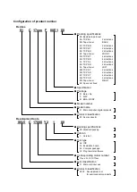
Страница 3: ...ections 0P TCP ST 4 directions 0Q TCP SD 4 directions 0R Tape reel RIGHT 99 Specs not fixed Specification Package D Bare chip F QFP B BGA WCSP Model number Model name C Microcontroller digital products Product classification S1 Semiconductor S5U1 C 17000 Y2 1 00 Development tools Packing specifications 00 Standard packing Version 1 Version 1 Tool type Hx ICE Tx Evaluation board Cx Compiler package...

Страница 4: ......

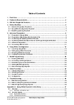
Страница 5: ...g Writer Configuration 12 6 1 Launching Gang Writer 12 6 2 Setting Gang Writer Parameters 13 6 3 Detecting ICDmini Connected 16 6 4 Loading Program Data to ICDmini 16 7 Multi Programming 20 7 1 Entering ID Number 20 7 2 Connecting with Target System 20 7 3 Establishing Connection with ICDmini 22 7 4 Starting Multi Programming 22 7 5 Disconnecting Target System 23 8 Other Functions 24 8 1 Individua...

Страница 6: ... 4 CheckTargetConnection 29 A 2 5 StartOperation 30 A 2 6 GetStatus 31 A 2 7 GetString 32 A 2 8 GetConnectedICD 33 A 2 9 LoadIcdFlsProgram 35 A 2 10 LoadIcdUserProgram 36 A 2 11 GetIcdStatus 37 A 3 Restrictions 39 A 4 Measurement Results 39 Appendix B List of Configurations by Model 40 Revision History 44 ...

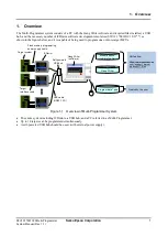
Страница 7: ...11 12 21 as shown in the figure below and it is capable of being used to program one or more target MCUs Figure 1 1 Overview of Multi Programmer System The entire system including ICDminis a USB hub and a PC referred to as Multi Programmer Up to 10 targets can be programmed simultaneously A self powered USB hub should be used with external power supply Obrtain from https www epsondevice com suppor...

Страница 8: ...quired Component Spec Requirements Remarks PC A PC with an Intel Pentium 4 1 50 GHz or higher CPU and 512 MB or more RAM included is recommended Supported OS Microsoft Windows To be provided by the user USB hub A self powered hub that is able to supply a maximum of 500 mA per port each ICDmini is required To be provided by the user ICDmini Prepare the necessary number of ICDminis for programming t...

Страница 9: ...r to Available ICDmini hardware version under Appendix B List of Configurations by Model for more information by model If you do not have an ICDmini of the version listed in that table contact our sales representative Note that a serial number must be programmed to the ICDmini if its version is 1 0 or 1 1 or if the firmware has been updated by the user ICDmini firmware The version supported depend...

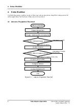
Страница 10: ...s of these steps are shown below 4 1 Advance Preparation Flowchart Figure 4 1 1 Advance Preparation Flowchart Prepare Gang Writer Prepare model specific information file Update firmware Program serial number Configure ICDmini Connect ICDmini to PC Advance preparation End Confirm ICDmini firmware version Confirm ICDmini hardware version Unnecessary to update Necessary to update Unnecessary to progr...

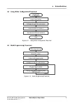
Страница 11: ...t 4 3 Multi Programming Flowchart Figure 4 3 1 Multi Programming Flowchart Launch Gang Writer Gang Writer configuration End Configure Gang Writer parameters Detect ICDmini connected Load data to ICDmini in advance Multi programming Enter ID number Connect with target system Establish connection with ICDmini Program target systems Change programmed target system with new one Repeated ...

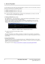
Страница 12: ...02 The same model specific information files as GNU17 S1C17 Family software development tool are included in the S5U1C17000Y23 package When the model specific information file of a model is updated or the file for a new model is added before being included to GNU17 the file name appears on the model list of the website independently If the model specific information file name for the model to be u...

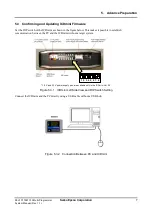
Страница 13: ...he figure below This makes it possible to establish communication between the PC and the ICDmini without a target system 1 8 V and 3 3 V power supply pins are available only in the ICDmini Ver 2 0 Figure 5 3 1 ICDmini Left Side View and DIP Switch Setting Connect the ICDmini and the PC directly using a USB cable without a USB hub Figure 5 3 2 Connection Between PC and ICDmini 1 2 3 4 5 6 7 8 ...

Страница 14: ...Dmini hardware and firmware version numbers Check to see if the firmware version is equal to or higher than that described in Available ICDmini firmware version under Appendix B List of Configurations by Model Figure 5 3 3 ICDmini Version Checker Execution Screen The example above shows the version number as follows Firmware Ver 3 2 S N is the serial number set to the ICDmini and hyphens are displ...

Страница 15: ... ICDmini hardware version under Appendix B List of Configurations by Model Programming serial number After connecting the ICDmini to the PC select EPSON MCU S1C17GangWriter C17SNwrite from the Start menu When Windows 7 or Vista is used right click on C17SNwrite and select Run as administrator When the window shown below opens enter the ICDmini serial number to the Serial No field and then click on...

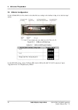
Страница 16: ... the target system 1 8 V and 3 3 V power supply pins are available only in the ICDmini Ver 2 0 Figure 5 5 1 ICDmini Left Side View Table 5 5 1 ICDmini DIP Switch Setting Target system interface voltage level Switch settings 3 3 V 1 8 V Voltage input from the target system For the DIP SW8 setting refer to ICDmini DIP switch SW8 FLASH VCC OUT connection under Appendix B List of Configurations by Mod...

Страница 17: ...ogrammer Seiko Epson Corporation 11 System Manual Rev 1 1 5 6 Connecting ICDmini to PC Connect the ICDminis and the PC via a USB hub after the preparation described above has been completed Figure 5 6 1 Connection Diagram Between PC and ICDminis ...

Страница 18: ...ON MCU S1C17GangWriter C17GangWriter from the Start menu of the PC When Windows 7 or Vista is used right click on C17GangWriter and select Run as administrator Figure 6 1 1 GangWriter Window Before loading the target program data to the ICDmini click on the Load Program To ICDmini button Then click on the Advanced button in the window opened to set parameters Figure 6 1 2 Load Program To ICDmini W...

Страница 19: ...rs in the dialog box shown below For the parameter setting values that depend on the model refer to Appendix B List of Configurations by Model Parameters 1 and 6 that specify file names are required to be entered in a full path Use the Browse button to select them from a file select dialog box Figure 6 2 1 Set Load Parameter Dialog Box 1 2 3 4 5 6 7 8 9 10 ...

Страница 20: ...d be set to a time required to erase and program the flash memory a margin in order to avoid a system freeze If the time required for erasing and programming the flash memory is unknown first set the maximum value and adjust it by confirming the actual programming time 5 Comment Enter any comments and or the commands shown below Up to 100 characters can be entered v Function Flash programming volt...

Страница 21: ...ry 8 End Block No of Erase Enter the erasing end block number of the flash memory in a decimal number Effective range 0 to 16 777 215 Enter 0 when erasing the entire flash memory 9 Flash Memory Top Address Enter the flash memory top address in a hexadecimal number Effective range 0x0 to 0xfffffe The prefix 0x or 0X is not necessary to enter Specify the address with an even number 10 Comment Enter ...

Страница 22: ...er detects the ICDminis connected to the PC their serial numbers are displayed in the ICDmini Serial No fields The ID No is a convenience number so that the programming status information displayed on the PC will correspond to each ICDmini Enter a unique value within 0 to 999 to each ID No field located to the right of the serial number displayed Figure 6 4 1 ID No Setting Then select the paramete...

Страница 23: ... for that ICDmini displays G00 COMPLETE with the background highlighted in green If the loading operation has failed the STATUS field for that ICDmini displays an error status message with the background highlighted in red Figure 6 4 3 Loading Program Data to ICDmini If the check is removed from the check box located to the left of the serial number Gang Writer does not load the program data to th...

Страница 24: ...figure the ICDminis with a unique serial number There are the same as ID No item two or more Two or more ID No fields have the same number entered Change them to a unique number Please set load parameter information The Parameter File field is empty and the parameters have not been configured in the Set Load Parameter dialog box yet Refer to 6 2 Setting Gang Writer Parameters and fill in the param...

Страница 25: ...An error has occurred during verify check after loading FLS to the ICDmini G27 FLS UNEXPECTED ERROR Unexpected error has occurred during loading FLS to the ICDmini G31 USER TIMEOUT ERROR A communication time out has occurred during loading the user program data to the ICDmini G32 USER FILE OPEN ERROR The user program data file cannot be opened G33 USER FILE FORMAT ERROR The user program data file ...

Страница 26: ...dow to associate the target numbers in the GangWriter window and the ICDminis connected to the PC Figure 7 1 1 ID Number Setting in Gang Writer Main Window 7 2 Connecting with Target System Each target system is connected to the 4 pin target interface connector and the 4 pin flash memory programming power supply connector of each ICDmini Figure 7 2 1 Connectors on ICDmini Left Side View 1 2 For ta...

Страница 27: ...gurations by Model to determine whether this pin is connected to the target MCU or not 2 GND Power supply ground Connect this pin to the ground of the target system 3 TARGET RST OUT O Target reset signal output Be sure to connect this pin to the reset pin on the target system 4 TARGET VCC IN I Target voltage input When an external power supply voltage 1 0 V to 5 5 V is used for interfacing between...

Страница 28: ...ress Enter on the keyboard The multi programming is executed in four steps RESET ERASE WRITE and VERIFY processes in order and the process being currently executed is indicated by the indicators LED symbols located at each target field that is blinking When each process has completed normally the corresponding indicator lights in green When multi programming for all the target systems has complete...

Страница 29: ...en an Error Occurred After an error has occurred entering the index number of the ICDmini in which an error occurred from the keyboard retries the process for the ICDmini For example to retry the process for index number 1 press the 1 key 7 5 Disconnecting Target System After turning power to the target systems off disconnect the programmed target systems and connect the new target systems to be p...

Страница 30: ...E WRITE and VERIFY processes from the top can be used to select the processes to be executed Selecting a check box will execute the process and clearing a check box skips the process Example Setting to execute the RESET and VERIFY processes in the target system index number 0 Figure 8 2 1 Selecting Execution Processes Individually The check box settings are saved and will also be effective at the ...

Страница 31: ...elect dialog box that appears by clicking on the Browse button Header Enter the leading characters of log files in the Header field This field can be left blank With the leading characters added the log file appears as follows Header YYYYMMDD txt If LOG is specified in Header and the current date is June 30 2014 the file name is as follows LOG20140630 txt The Folder and Header settings will take e...

Страница 32: ...efer to 7 2 Connecting with Target System 2 Noise may cause an error Make sure that the wiring length between the target MCU and the ICDmini is as short as possible roughly 15 cm or shorter Provide a countermeasure against noise for the wiring pattern on the target board 3 There may be a difference in the interface voltage between the target system and the ICDmini Set the DIP switch on the ICDmini...

Страница 33: ...tablishes a connection with the ICDmini Execute this function the number of times for the number of ICDminis to be used Replace the target systems ResetTarget Issues a target reset GetStatus Monitors the end of target reset CheckTargetConnection Issues confirmation of connection with the target IC GetStatus Monitors the end of confirmation of connection with the target IC StartOperation Executes t...

Страница 34: ...eds or fails Format long OpenIcdConnection long IcdDeviceNumber Argument IcdDeviceNumber ICDmini ID number 0 to 999 Return values OK ERROR_PARAMETER ERROR_ICD_OPEN_CONNECTION A 2 2 CloseIcdConnection Function Corresponds to OpenIcdConnection and closes communication with the ICDmini Control is not returned until this function either succeeds or fails Format long CloseIcdConnection long IcdDeviceNu...

Страница 35: ...ormat long ResetTarget long IcdDeviceNumber Argument IcdDeviceNumber ICDmini ID number 0 to 999 Return values OK NG ERROR_PARAMETER ERROR_ICD_CONNECTION A 2 4 CheckTargetConnection Function Confirms connection with the target system Time out is 1 second Control is returned immediately after this function is called Monitor the end of the operation with the GetStatus function Format long CheckTarget...

Страница 36: ...OK when all operations are finished Format long StartOperation long IcdDeviceNumber long IcdOperation long TimeOut Arguments IcdDeviceNumber ICDmini ID number 0 to 999 IcdOperation Sets the operation to execute bit 0 Target Reset 1 Executed 0 Not executed bit 1 Erasing flash memory 1 Executed 0 Not executed bit 2 Programming flash memory 1 Executed 0 Not executed bit 3 Verifying flash memory 1 Exe...

Страница 37: ...rence address is stored ResetTarget Fixed at 0 CheckTargetConnection Fixed at 0 StartErase Erase start address StartWrite Error occurrence address StartVerify Error occurrence address Return values OK OPERATION_TARGET_CONNECTION OPERATION_TARGET_RESET OPERATION_ERASE OPERATION_WRITE OPERATION_VERIFY ERROR_PARAMETER ERROR_TIMEOUT_TARGET_CONNECTION ERROR_TIMEOUT_TARGET_RESET ERROR_TIMEOUT_ERASE ERRO...

Страница 38: ...ts the return code to a character string Format long GetString long ReturnedCode char ReturnedString Arguments ReturnedCode Return code ReturnedString The character string after converting the return code is stored The caller must allocate 256 bytes for this area Invalid returned code is returned if an invalid return code is specified Return values OK NG ...

Страница 39: ...serCommentBufferCount Returns the number of buffers for the user program comments that must be allocated by the caller long TakenCount Returns the maximum number of serial numbers that can be acquired long ConnecttedCount Returns the number of ICDminis currently connected via USB When the function is called with IcdSerialNumberList set to other than NULL short IcdSerialNumberList Buffer address fo...

Страница 40: ... 5 as the characters preceding the space are effective 3 If the comment begins with 123 it is regarded as that this comment has no ID included as there is no character preceding a space Time Out The comment may set the time out value for erasing and programming of the flash memory Note that an ID number must be placed at the beginning Example 123 T60 The ID number is 123 and the time out value is ...

Страница 41: ...icode It should be terminated with NULL long EraseAddress Erase routine address long WriteAddress Write routine address long IcdDeviceNumber ID number 0 to 999 long TimeOut Time out value seconds char Comment Comments It should be terminated with NULL The comment length including ID number and time out value must be within 127 bytes excluding NULL Return values OK ERROR_EXECUTING ERROR_PARAMETER E...

Страница 42: ... and terminated with NULL short FileName User program file name in a full path Unicode It should be terminated with NULL long EraseBlockStart Erasing start block number long EraseBlockEnd Erasing end block number long FlashAddress Flash memory top address char Comment Comments It should be terminated with NULL The comment length must be within 127 bytes excluding NULL Return values OK ERROR_EXECUT...

Страница 43: ...number of bytes of which programming has completed Return values OK OPERATION_FLS_ICD_ERASE OPERATION_FLS_ICD_WRITE OPERATION_FLS_ICD_VERIFY OPERATION_USER_ICD_ERASE OPERATION_USER_ICD_WRITE OPERATION_USER_ICD_VERIFY ERROR_PARAMETER ERROR_TIMEOUT_FLS_ICD ERROR_TIMEOUT_USER_ICD ERROR_MOT_OPEN_FLS ERROR_MOT_FORMAT_FLS ERROR_MOT_SIZE_OVER_FLS ERROR_MOT_ADDR_FLS ERROR_MOT_OPEN_USER_PRG ERROR_MOT_FORMA...

Страница 44: ...UF 0x51 The serial number buffer size is insufficient ERROR_INSUFFICIENT_IDNUMBUF 0x52 The ID number buffer size is insufficient ERROR_INSUFFICIENT_FLSCOMMENTBUF 0x53 The FLS comment buffer size is insufficient ERROR_INSUFFICIENT_USERCOMMENTBUF 0x54 The user program comment buffer size is insufficient ERROR_MOT_OPEN_FLS 0x60 The FLS program file in the Motorola format cannot be opened ERROR_MOT_FO...

Страница 45: ...st connected is recognized A 4 Measurement Results For reference the table below lists the measured times required for loading a 3M bytes of user program sa from the PC to the ICDmini Table A 4 1 ICDmini Loading Time List Operation Time Erasing 34 seconds Loading 1 minute 36 seconds Verifying 3 minutes 14 seconds Total time 5 minutes 24 seconds When the user program is loaded using the LoadIcdUser...

Страница 46: ... 2 0 3 0 or later ON Connect VPP 5 fwr17554_highv11 saf 0xa2 0x6c 60 v7 5 7 0 1 32 0x8000 2 0 3 0 or later ON Connect VPP 6 S1C17555 fwr17555_2kbv11 saf 0x42 0x76 60 v7 5 7 5 s128 1 64 0x8000 2 0 3 3 or later ON Connect VPP 7 fwr17555_128bv11 saf 0x42 0x76 60 s128 1 64 0x8000 1 0 1 1 2 0 3 3 or later OFF No connection 8 S1C17564 fwr17564v11 saf 0x9c 0x68 60 v7 5 7 0 1 32 0x8000 2 0 3 3 or later ON...

Страница 47: ...OFF No connection S1C17651 fwr17651v11_4 saf 0x9c 0x68 60 v7 5 7 0 s128 1 4 0x8000 2 0 3 3 or later ON Connect VPP S1C17653 fwr17653v11_4 saf 0x9c 0x68 60 v7 5 7 0 s128 1 4 0x8000 2 0 3 3 or later ON Connect VPP S1C17656 fwr17656v11 saf 0xcc 0xc4 60 v7 5 7 5 s128 0 0 0x8000 2 0 3 3 or later ON Connect VPP S1C17701 fwr17701v11 saf 0x48 0x80 60 0 0 0x8000 1 0 1 1 2 0 3 0 or later OFF No connection S...

Страница 48: ...2 0x76 60 s128 1 64 0x8000 1 0 1 1 2 0 3 3 or later OFF No connection 8 S1C17F13 fwr17f13_2kbv11 saf 0x50 0x84 60 v7 5 7 5 0 0 0x8000 2 0 3 0 or later ON Connect to VPP 7 fwr17f13_128bv11 saf 0x50 0x84 60 0 0 0x8000 1 0 1 1 2 0 3 0 or later OFF No connection 8 S1C17F57 fwr17f57v11 saf 0x9c 0x68 60 v7 5 7 0 s128 1 8 0x8000 2 0 3 3 or later ON Connect to VPP S1C17M01 fwr17m01v11 saf 0x42 0x76 60 v7 ...

Страница 49: ... 0 3 3 or later ON Connect to VPP S1C17W23 fwr17w23v11 saf 0x48 0x7c 60 v7 5 7 5 0 0 0x8000 2 0 3 3 or later ON Connect to VPP Note 1 The files are stored in the C EPSON C17GangWriter mcu_model folder default by model 2 Time out time Although any time can be set the table lists the maximum time 3 This column shows the ICDmini DIP switch SW8 setting and whether the FLASH VCC OUT pin of the flash me...

Страница 50: ...story Attachment 1 Rev No Date Page Category Contents Rev 1 0 2014 11 10 All New New establishment Rev 1 1 2016 05 02 8 Revise Note is added for the USB driver Rev 1 1 2016 05 02 40 43 Revice The support MCU model is added Rev 1 1 2016 05 09 2 Revise Description of supported OS ...

Страница 51: ...CH 12F Dawning Mansion Keji South 12th Road Hi Tech Park Shenzhen 518057 CHINA Phone 86 755 2699 3828 FAX 86 755 2699 3838 EPSON TAIWAN TECHNOLOGY TRADING LTD 14F No 7 Song Ren Road Taipei 110 TAIWAN Phone 886 2 8786 6688 FAX 886 2 8786 6660 EPSON SINGAPORE PTE LTD 1 HarbourFront Place 03 02 HarbourFront Tower One Singapore 098633 Phone 65 6586 5500 FAX 65 6271 3182 SEIKO EPSON CORP KOREA OFFICE 1...

Отзывы: