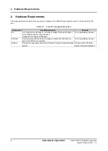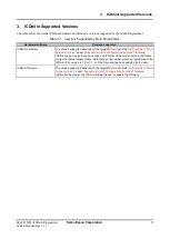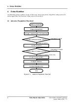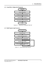
5. Advance Preparation
10
Seiko Epson Corporation
S5U1C17001Y23 Multi-Programmer
System Manual (Rev. 1.1)
5.5 ICDmini Configuration
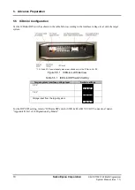
Set the ICDmini DIP switch as shown in the table below according to the interface voltage level with the target
system.
* 1.8 V and 3.3 V power supply pins are available only in the ICDmini Ver. 2.0.
Figure 5.5.1
ICDmini Left Side View
Table 5.5.1 ICDmini DIP Switch Setting
Target system interface voltage level
Switch settings
3.3 V
1.8 V
Voltage input from the target system
For the DIP SW8 setting, refer to “ICDmini DIP switch (SW8) & FLASH VCC OUT connection” under
“Appendix B List of Configurations by Model.”
1 2 3 4 5 6 7 8
1 2 3 4 5 6 7 8
1 2 3 4 5 6 7 8

