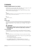
background image

2-72

   Setup

Rev. C

Confidential

Printing Using Windows

It is possible to print to the dedicated printer unit of the IR-320 using Windows.

Note:

Before executing a test printout from Windows, set up the dedicated printer unit correctly and confirm the 
operation using the Device Diagnostics Utility. If it does not set up correctly, the test printout from 
Windows is not executed normally. Refer to “Installing a Dedicated Printer Unit” for the setup procedure 
and the operating confirmation procedure of the Device Diagnostics Utility.   

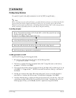
Operating progress 

Installing procedure of APD

Install the APD using the following procedure.

1. Start up the system and execute the driver of the following folder. 

C:\BACKUP\APDRV\******.EXE

2. The License Agreement dialog is displayed. Select the “I accept the terms in the License 

agreement.” check box, click NEXT.

3. The Location to Save Files dialog is displayed. Choose the folder in the installation place and 

click NEXT.  C:\Program Files\..\EPSON Advanced Printer Driver\Setup\ are chosen in 
the default.

4. The file is extracted and the Select OS dialog is displayed. Choose your OS in the Select 

Install OS box. Confirm  that US is chosen  in  Select Install Language. Click NEXT.

5. The Select Module dialog is displayed. Choose the printer driver to install. Also, choose the 

overwriting condition of the file in Universal Driver Overwrite.  The printer driver has the 
following types. When you click Finish, the file is copied into the specified folder.

Refer to “Installing a Dedicated Printer Unit”

Set up the dedicated printer unit to the IR-320; confirm the operation by using

Install the APD (Advanced Printer Driver)

Setup the APD and print the status sheet of the printer using the test.

Print from Windows application using the test.

the Device Diagnostics Utility.

Содержание IR-320

Страница 1: ...Technical Reference Manual IR 320 Issued Date Issued by EPSON English 404368102 ...

Страница 2: ......

Страница 3: ...nformation in the document You may not reproduce store or transmit the confidential information in any form or by any means electronic mechanical photocopying recording or otherwise without the prior written permission of Seiko Epson Your obligations under this Agreement are in addition to any other legal obligations Seiko Epson does not waive any right under this Agreement by failing to exercise ...

Страница 4: ...on Microsoft MS DOS Windows and Windows NT are registered trademarks of Microsoft Corporation CompactFlash is a trademark of SanDisk Corporation BaySwap is a trademark of Phoenix Technologies Ltd General Notice Other product and company names used herein are for identification purposes only and may be trademarks of their respective companies ...

Страница 5: ...t release Rev B 1 16 Change the DSW1 settings 3 25 Add the OS Recovery method of step 4 B 3 Add the Jumper and Switch Settings Rev C 3 65 66 67 68 69 5 1 14 15 16 27 Add the HDD Power Down Settings 5 1 12 14 15 16 25 27 Add the BIOS Ver 2 11 02 1 18 19 20 21 Change the Dimensions 5 12 25 Add the Onboard Lan Boot ROM ...

Страница 6: ...the main power switch immediately and unplug the power cable if the IR 320 produces smoke a strange odor or unusual noise Continued use may lead to fire or electric shock Contact your dealer or an EPSON service center for advice Never disassemble or modify this product Tampering with this product may result in injury fire or electric shock Never install this product and connect the cable while occ...

Страница 7: ... the prongs If you leave the power plug in the outlet for a long time dust may collect on the base of the prongs causing a short and fire CAUTION Do not connect devices other than those specified in this manual Doing so may result in fire or improper operation Do not set this product in the unstable place such as on a shaky stand or a place that is not level The product may break or cause injury i...

Страница 8: ...tly Always connect the power cable to the AC inlet of this product before plugging it into the wall outlet Be sure to push the plug of the power cable into the AC inlet of this product When the power cable for the TM printer is connected do not short circuit its connector pins Because pins are exposed this connector may lead to the short circuit when not connected to the TM printer Do not insert f...

Страница 9: ...al Aim of the Manual This manual was created to provide information on the IR 320 for anyone who is developing applications Contents of the Manual The table below is just a summary A complete table of contents appears at the end of this section See it for detailed information and page numbers The configuration of the manual is as follows Chapter 1 IR 320 System Overview Describes the hardware conf...

Страница 10: ...ndix B IR 310 versus IR 320 Describes differences between the IR 310 and IR 320 Appendix C Serial Handshaking Describes the Serial Handshaking Related Manuals Name Comments IR 320 User s Manual Describes the basic setup and operation procedure IR 320 Service Manual Describes the maintenance and repair procedure for IR 320 service engineers ...

Страница 11: ... and Self Diagnosis Functions 1 9 Operating Systems 1 9 Utilities 1 9 Operation Modes 1 10 1 Mechanical Off Mode 1 10 2 Soft Off Mode 1 10 3 Full On Mode 1 10 4 Video Off Mode 1 10 5 Suspend Mode 1 11 Jumper Locations and Settings 1 13 Main Board Jumpers 1 13 POS 320 Board Jumpers 1 15 Functions of SW2 1 17 IR 320 Usage 1 18 Dimensions 1 18 Main Body 1 18 Peripheral Dimensions of the LCD 1 19 Peri...

Страница 12: ...7 Installing a Cash Drawer 2 68 Attaching a Power Cable 2 69 Installing Peripheral Devices to the COM Port 2 70 Setup 2 70 Printing Using Windows 2 72 Chapter 3 OS and Drivers Outline of This Chapter 3 1 Operating Systems 3 1 Drivers and Utilities 3 1 Windows 2000 Pre Installed Model 3 4 Installation Procedure 3 4 Directory Configuration 3 6 Windows 2000 Setup Procedure 3 7 Setting the recognition...

Страница 13: ...r 3 44 Installing the Touch Panel Driver 3 44 Installation for Windows 98 Locally Procured Edition 3 46 Installation Procedure 3 46 Setup Procedure 3 47 Installing the Chipset Driver for Intel 3 47 Ultra DMA Setting for the HDD 3 48 Installing the Network Driver 3 49 Installing the Video Driver 3 50 Installing the Sound Driver 3 51 Installing the Touch Panel Driver 3 51 Installing the AC line tool...

Страница 14: ...Setting the Utility 4 30 84 key Configuration Utility for Windows XP 2000 NT 98 4 43 Start 4 43 Speed Buttons 4 44 Key Definitions 4 45 Setting the Key Label 4 45 Keytop Color Settings 4 46 Key Program 4 46 Saving the Settings 4 46 Loading the Settings 4 46 New 4 47 Keytop View 4 47 Printing the Settings 4 47 Exit 4 47 Automatic Definition Data Setting Utility for Windows XP 2000 NT 98 4 48 Functi...

Страница 15: ...ons BIOS Functions Restrictions 5 1 HDD Power Down Timer Setting 5 1 BIOS Setup 5 2 Operating Procedure 5 2 Troubleshooting 5 3 Changing settings 5 3 BIOS Setup Main Menu 5 4 Standard CMOS Features Menu 5 5 Advanced BIOS Features Menu 5 7 Advanced Chipset Features Menu 5 10 Integrated Peripherals Menu 5 11 Power Management Setup Menu 5 13 Supplementary Explanation for Power Management 5 15 PNP PCI...

Страница 16: ...tings A 2 BIOS Settings A 2 Wake On LAN Method Details A 3 Magic Packet Received A 3 Reference Information A 3 MAC Address A 3 Appendix B The IR 310 Compared to the IR 320 Hardware B 1 Hardware Configuration B 3 Jumper and Switch Settings B 3 Option Comparison B 4 Software Comparison B 5 Comparison for Driver Tool and Utility B 6 Appendix C Serial Handshaking Overview of the TM Printer and the Cus...

Страница 17: ...ombinations of an operating system CPU HDD CD ROM drive LCD unit and printer Please contact your dealer for details Unpacking For the unpacking see the User s Manual packed with the system IR 320 Features Simplicity Employing the touch panel enables even a beginner to operate the product easily It is possible to learn how to use the system in a very short time It is designed for quick and easy set...

Страница 18: ... has an AC outlet that can work together with the system Security Data can be protected from being stolen by key locking of the front cover Six access levels can be set by using different types of manager keys Owners or managers can set different levels of access to the system The battery backup option can prevent data from being lost due to a power out High performance Power and speed needed for ...

Страница 19: ...Overview 1 3 IR 320 Technical Reference Manual Part Names The figures below show the part names of the IR 320 DM LR121Series eries eries eries LCD Display Unit LCD brightness adjustment buttons HDD LED POWER LED lock lever ...

Страница 20: ...omer display option main power switch MSR unit option front cover keylock soft power switch lock switch paper FEED button printer unit option POWER LED HDD LED LCD unit option front cover key lock main power switch side cover USB keyboard mouse connector rear cover ...

Страница 21: ... C IR 320 System Overview 1 5 IR 320 Technical Reference Manual CD ROM CD R RW Drive OI R06 Front CompactFlash Drive OI R07 reset switch volume CD ROM CD R RW drive eject button front CompactFlash adapter ...

Страница 22: ...R 320 Main power switch KB mouse LPT port AC inlet COM5 port COM6 port COM2 port Fuse AC outlet Customer display switch Customer display connector TM power connector Drawer kick connector PCI slots LAN LEDs Ethernet connector USB connector COM1 port Display connector Line In MIC Line Out MSR USB ...

Страница 23: ...hout Rear Cover An AC outlet max 3A that is on whenever the system is on Model Configurations The IR 320 can be configured with the following optional units LCD units with touch panel SVGA LCD unit with touch panel 264 mm 10 4 color TFT Model name DM LR104T 310 mm 12 2 color TFT Model name DM LR121SL 310 mm 12 2 color TFT Model name DM LR121SV POS keyboard units 84 key Model name DM KR084 28 key M...

Страница 24: ...00 series Model name TM T88II series External mounting type Model name TM U675 series Model name TM T285 series Model name TM H5000 series Operation Testing Products for IR The Operation Confirmed items are marketed by EPSON and are built in included or connected to an EPSON POS product and operation by has been confirmed by EPSON EPSON can also offer reference information for the selection of per...

Страница 25: ...ion can select the EPSON pre installed HDD The IR 320 Driver CD ROM that includes an appropriate driver for an operating system is included See OS Information in Chapter 3 Note The USB interface is not supported by Windows NT and MS DOS Windows NT supports the USB Keyboard Be sure to make the recovery media and back up the data See Recovering the OS in Chapter 3 for details When you need to repair...

Страница 26: ...ull on mode is produced To turn off the IR 320 power turn the power off from the software The power off operation differs slightly depending on the setting of the APM driver See Chapter 4 Utility 4 Video Off Mode When no input operation is performed for a given period of time during operation in the full on mode only the LCD and the backlight circuits are turned off thus extending the service life...

Страница 27: ...lock is delayed In the suspend mode the mode is immediately reset to the full on mode when input is received from the keyboard mouse HDD FDD or touch panel Also the suspend mode is always changed to the full on mode when the soft power switch is pressed regardless of the BIOS switch setting Type of OS OS Setting BIOS Soft Off by PWR BTTN setting Instant Off Delay 4 Sec Disabled Windows XP Shutdown...

Страница 28: ... by pressing the soft power switch if the dedicated APM driver is used e Transfer to the video off mode after no input operation for a specified period or selection of video off mode at Operation System f Input operation from keyboard mouse or touch panel Reset by pressing the soft power switch if the dedicated APM driver is used g Main power switch off or forced power off because of AC power cuto...

Страница 29: ...Rev C IR 320 System Overview 1 13 IR 320 Technical Reference Manual Jumper Locations and Settings Main Board Jumpers The figure below shows the locations of the main board connectors and jumpers ...

Страница 30: ...ngeable JP31 1 2 TM reset polarity setting See JP31 settings TM reset polarity settings on page 1 15 JP32 1 2 TM customer display flow control See JP32 settings TM customer display flow control on page 1 15 JP5 settings RTC and CMOS clear JP5 RTC clear 1 2 default Normal operations 2 3 Clear Settings for JP7 to 18 COM1 COM2 COM5 COM6 power output Jumper short circuited Pin 1 function in the DB9 co...

Страница 31: ...ers The POS circuit board unit has two jumpers one switch and one four polarity DIP switch that can be set Parts Side faces down when installing into the IR 320 Back Side JP31 settings TM reset polarity settings JP31 Dedicated TM reset 1 2 default Active LOW 2 3 Active HIGH JP32 settings TM customer display flow control JP32 Dedicated TM flow control Customer display flow control Dedicated TM rese...

Страница 32: ...and 28 key and 84 key default settings when the settings are initialized and during an enforced boot start up JP3 Use this jumper to make a TM printer reset using RTS or DTR effective DSW1 Use this DIP switch to select the default value of the country mode of the MSR And also use the switch when the keyboard cannot be used due to a setting error JP3 settings TM reset enable disable setting for RTS...

Страница 33: ...s a TM printer without attaching a customer display Normally set this switch to the 0 side LCD setting jumper switch The LCD setting jumper switch is located on the POS 320 board Functions of SW2 Customer display loop back jumper Dedicated TM reset 1 side Loop back DTR and DSR 0 side default Normally used LCD jumper switch settings LCD setting jumper LCD units 1 2 DM LR104T 252 LR121SL LR121SV 2 3...

Страница 34: ...1 18 IR 320 System Overview Rev C IR 320 Usage See the IR 320 User s Manual Dimensions Main Body 252 mm 9 9 271 mm 10 7 386 mm 15 2 454 5 mm 17 9 ...

Страница 35: ...d the 104 type is the case size of the DM LR104T 329 mm 13 0 DM D500 306 mm 12 1 DM D110 541 mm 21 3 DM D500 518 mm 20 4 DM D110 454 5 mm 17 9 121Type 490mm 19 3 104Type 460 mm 18 1 121Type 555mm 21 9 104Type 521 mm 20 5 121Type 317mm 12 5 104Type 297 mm 11 7 121Type 295mm 11 6 104Type 266 mm 10 5 121Type 310mm 104Type 276 mm 121Type 255mm 104Type 320 mm 121Type 425mm 104Type 390 mm 121Type 249mm ...

Страница 36: ...stomer Display The dimensions in indicate the dimensions of the DP 504 with the extension prop Peripheral Dimensions of the Printer Tray Dimensions when the OI R101 001 is mounted 129 mm DP 504 227 mm 5 1 8 9 DM D500 83mm 3 3 DM D110 69 mm 2 7 178 mm 7 0 263 mm 10 4 ...

Страница 37: ...320 Technical Reference Manual Dimensions when the dedicated printer TM H6000 is attached to the OI R01 022 Dimensions When the Printer Unit is Mounted 368 mm 14 5 40 mm 1 6 TM T88IIIR 262mm 10 3 TM U210AR 283mm 11 1 TM H3000R 327 mm 12 9 ...

Страница 38: ...1 22 IR 320 System Overview Rev C ...

Страница 39: ...e correctly if the installation order of OS and driver is not correct The basic flow of the setup is described below Installing OS Installing OS Installing the dedicated customer display the cash Operating confirmation with The setup completion Installing the 28 84 Keyboard MSR Setting the keyboard firmware with the keyboard firmware setting utility Making the Setting to define automatically for m...

Страница 40: ...is installed and the power is on do not turn off the main side power switch or unplug the power cable until you put the IR 320 in the soft off mode with the soft front power switch Then you can turn off the main power switch and unplug the power cable If the main power switch is turned off or the power cable is unplugged when the unit is in full on mode power starts flowing from the battery unit I...

Страница 41: ...called soft off Proceed to step 4 If the power does not go off proceed to step 4 3 Press the soft power switch again and hold it down for 4 seconds or more The power supply to the IR 320 will go off 4 Turn off the main side power switch The resulting power off condition is called mechanical off 5 When the battery unit is attached remove it 6 Unplug the power cable Confirm that power supplies to al...

Страница 42: ... Installing a 2 5 HDD Unit OI HDD 1 2 7 Installing a 3 5 HDD Unit OI HDD 1 2 11 Installing a CD ROM Drive CD R RW Drive OI R06 2 2 17 Installing a Front CompactFlash Card Adapter OI R07 2 2 21 Installing an LCD Unit 2 24 Installing an 84 Key Keyboard Unit DM KR084 DM KR084 2 35 Installing a Battery Unit OI R03 2 39 Installing a 28 Key Keyboard Unit DM K028 2 43 Installing the MSR Unit DM MR123 2 4...

Страница 43: ...al surface to discharge the static electricity in your body It is also recommended that you wear a grounded wristband and work on an antistatic surface Do not touch the DIMM connectors Dirt may cause a malfunction If it is difficult to insert the DIMM do not apply excessive force to the DIMM If excessive force is used the connection parts may be damaged Remove the DIMM check the connection part to...

Страница 44: ...h the DIMM until it clicks and stands upright Note When two DIMMs are installed use the farthest socket first 4 Reattach the side panel with two screws 5 Reattach the side cover Removing the DIMM To remove the DIMM unlock the lock pins located on both sides of the DIMM socket and pull the DIMM straight up ...

Страница 45: ...R 320 install the optional HDD and reinstall original the HDD unit in the IR 320 Install the optional HDD using the following procedure CAUTION Do not subject the HDD unit to shock or vibration Because the HDD unit is a precision instrument do not subject it to even the slightest shock or vibration 1 Removing the HDD unit 1 Open the front cover of the IR 320 If the front cover is locked unlock it ...

Страница 46: ...om the HDD unit 4 Pull the HDD unit toward the front slightly while watching the cables and remove the two cables for the HDD unit from the their connectors 5 Remove the HDD unit 6 Remove the four screws from the HDD unit and remove the HDD plate HDD plate ...

Страница 47: ...a master and the other a slave To make an HDD a master drive remove the jumper To make an HDD a slave set the jumper Note When you use two drives one must be a master and one must be a slave The IR 320 will not boot from the slave drive An HDD may be set to either a master or slave whether it is installed in the upper drive bay or the lower drive bay removing the HDD in the lower drive bay removin...

Страница 48: ...nstalling the HDD unit where the cables will be hidden later in this section 1 Push the HDD unit into the IR 320 from the front Be careful not to subject the HDD to shock or vibration and be sure the cables are not pinched Confirm that the projection on the mounting plate under the HDD is firmly engaged with the frame projection on the IR 320 2 Connect the two cables for the HDD unit to their conn...

Страница 49: ...its specifications Up to two 2 5 HDDs can be installed For information on installing the 2 5 HDD units OI HDD see the previous section Installing a 2 5 HDD Unit OI HDD The IR 320 does not start up though the battery unit OI R03 as the option is connected to the IR 320 To install the 3 5 HDD remove the currently installed HDD unit from the IR 320 install the optional HDD in the HDD unit and reinsta...

Страница 50: ...he front cover of the IR 320 If the front cover is locked unlock it with the key You may need to press in slightly as you turn the key 2 Open the HDD cover by lightly pressing down on the upper pin lock 3 Unscrew two screws and remove the HDD faceplate front cover ...

Страница 51: ... Reference Manual Confidential 4 Remove the left side cover by sliding it downward 5 Remove the two screws attaching the side panel 6 If a PCI card is installed remove it Remove the screw locking the PCI card and pull the PCI card out ...

Страница 52: ...e the two cables for the HDD unit from their connectors 8 Remove the HDD unit from the front while watching the cables 9 Remove the two cables from the HDD unit 10 Remove the four screws from the HDD unit and remove the HDD mounting plate ...

Страница 53: ...nstall the HDD using the following procedure 1 Attach the HDD to the HDD mounting plate with four screws 2 Set the HDD jumper as shown in the below figure The jumper setting depends on the make and model of the HDD Set the jumper for your HDD 3 Connect the two cables to their connectors ...

Страница 54: ...ful not to subject it to shock or vibration and be sure the cables are not pinched Confirm that the projection on the mounting plate under the HDD is firmly engaged with the frame projection on the IR 320 2 Connect the two cables for the HDD unit to their connectors frame projection projection on the HDD mounting plate ...

Страница 55: ...cover 8 Close the front cover 9 Turn on the IR 320 start up the BIOS setup and confirm that the HDD is identified normally For information on the BIOS setup see Chapter 5 BIOS Functions Installing a CD ROM Drive CD R RW Drive OI R06 The optional 24 CD ROM drive OI R06 or CD R RW drive OI R06 202 is installed using the following procedure Note The CD R RW drive can write but you must prepare the ap...

Страница 56: ...D R RW drive may stop operating Install the CD ROM CD R RW drive by following the steps below 1 Open the front cover of the IR 320 If the front cover is locked unlock it with the key You may need to press in slightly as you turn the key 2 Remove the HDD cover 3 Remove the CD ROM cover Keep this cover because it is not used while the CD ROM CD R RW drive is installed front cover ...

Страница 57: ... Setup 2 19 IR 320 Technical Reference Manual Confidential 4 Remove the left side cover by sliding it downward 5 Remove two screws attaching the side panel 6 Attach the cable set to the CD ROM CD R RW drive ...

Страница 58: ...engaged with the frame projection on the IR 320 If the cable for the HDD unit is in the way of the connection for the CD ROM CD R RW drive remove the HDD unit cable connect the cable for the CD ROM CD R RW drive and re connect the HDD unit cable 8 Connect the cable for the CD ROM CD R RW drive to the connector 9 Attach the CD ROM CD R RW drive with one screw 10 Reattach the HDD cover frame project...

Страница 59: ...so handle it gently When you remove and install the front CompactFlash card adapter be careful not to subject it to small shock vibration or bending because this may damage it Card type One Type I or Type II Power supply 3 3 V 50 mA max I F mode True IDE mode Connection to the main body Secondary IDE bus master connection 1 Open the front cover of the IR 320 If the front cover is locked unlock it ...

Страница 60: ...move the HDD cover 3 Remove the CD ROM cover Keep this cover because it is not used while the front CompactFlash card adapter is installed 4 Remove the left side cover by sliding it downward 5 Remove two screws attaching the side panel ...

Страница 61: ...e frame projection on the IR 320 If the cable for the HDD unit is in the way of the connection for the front CompactFlash card adapter remove the HDD unit cable connect the cable for the front CompactFlash card adapter and re connect the HDD unit cable 7 Attach the front CompactFlash card adapter with one screw 8 Connect the cable for the front CompactFlash card adapter to the connector 9 Reattach...

Страница 62: ...the type of the LCD unit and install when the OS is installed Note When you connect another type of the LCD unit you need to install another touch panel driver For details ask your dealer LCD unit Type Display size Resolution DM LR104T TFT 10 4 26 42 cm SVGA 800x600 DM LR121SL TFT 12 1 30 73 cm SVGA 800x600 DM LR121SV TFT 12 1 30 73 cm SVGA 800x600 Description of jumper switch for each LCD unit LC...

Страница 63: ... cover by sliding it downward 2 Remove the two screws from the printer unit or the printer tray 3 Remove the printer unit or the printer tray When removing the printer unit remove the printer cable from the connector 4 Thread the two cables for the LCD unit through the hole in the center of the IR 320 ...

Страница 64: ...ctor cable and a 38 pin connector cable Attach the ferrite core an accessory of the IR 320 to the 34 pin connector cable 7 Connect the cables for the LCD unit to their connectors 8 Check the Jumper Switch setting For the DM LR121SV DM LR121SL set the JP1 to 1 2 9 Install the printer unit or the printer tray and lock it with two screws 10 Reattach the side cover groove in the LCD unit tab on the IR...

Страница 65: ...left side cover by sliding it downward 2 Remove the two screws from the printer unit or the printer tray 3 Remove the printer unit or the printer tray When removing the printer unit remove the printer cable from the connector 4 Set the lock knob under the LCD unit to the release position ...

Страница 66: ...bs on the IR 320 with the right and left grooves in the back of the LCD unit When both sides are engaged slide the LCD unit down on the back 7 The LCD unit has a 34 pin connector cable and a 38 pin connector cable Attach the ferrite core an accessory of the IR 320 to the 34 pin connector cable groove in the LCD unit tab on the IR 320 ferrite core ...

Страница 67: ...t the JP1 to 1 2 and for the DM LR104T 052 set the JP1 to 2 3 Note If the jumper is incorrectly set the LCD display is not correct 10 Return the lock knob under the LCD unit to the lock position 11 Install the printer unit or the printer tray and lock it with two screws 12 Reattach the side cover POS board CN51 CN31 38 pin CN35 34 pin JP1 layout of the connectors Jumper Switch ...

Страница 68: ...s on the type of LCD unit DM LR121Series 1 Remove the left side cover by sliding it downward 2 Remove the two screws from the printer unit or the printer tray 3 Remove the printer unit or the printer tray When removing the printer unit remove the printer cable from the connector printer cable ...

Страница 69: ...tup 2 31 IR 320 Technical Reference Manual Confidential 4 Remove the two cables for the LCD unit from their connectors 5 Remove the ferrite core Keep the removed ferrite core for installing on another LCD unit ...

Страница 70: ... in the direction of the arrow and slide the LCD unit upward further on the back Adjust the position of the LCD unit while watching the hole shown in the figure so that the tabs of the main body can be disengaged from the grooves in the LCD unit Remove the LCD unit in the direction of arrow 5 DM LR104T 1 Remove the left side cover by sliding it downward 2 Remove the two screws from the printer uni...

Страница 71: ...he printer unit or the printer tray When removing the printer unit remove the printer cable from the connector 4 Remove the two cables for the LCD unit from their respective connectors 5 Remove the ferrite core Keep the removed ferrite core for installing on another LCD unit ...

Страница 72: ...range Slightly pull the part circled in the illustration below in the direction of the arrow and slide the LCD unit upward further on the back Adjust the position of the LCD unit while watching the hole shown in the illustration below so that the tabs of the main body can be disengaged from the grooves in the LCD unit Remove the LCD unit in the direction of arrow 4 ...

Страница 73: ...e 84 key keyboard is installed by using the following procedure 1 Remove the left side cover by sliding it downward 2 Remove the two screws from the printer unit or the printer tray 3 Remove the printer unit or the printer tray When removing the printer unit remove the printer cable from the connector 4 Set the lock knob under the 84 key keyboard to the release position ...

Страница 74: ...s on the IR 320 When both sides are engaged slide the LCD unit down on the back for installation 7 Connect the 38 pin connector cable for the 84 key keyboard to connector CN31 8 Set the Jumper Switch JP1 to 1 2 9 Return the lock knob under the 84 key keyboard to the lock position groove of the 84 key keyboard tab on the IR 320 POS board CN51 CN31 38 pin CN35 34 pin JP1 layout of the connectors Jum...

Страница 75: ...ith two screws 11 Reattach the side cover Removing an 84 Key Keyboard Unit 1 Remove the left side cover by sliding it downward 2 Remove the two screws from the printer unit or the printer tray 3 Remove the printer unit or the printer tray When removing the printer unit remove the printer cable from the connector printer cable ...

Страница 76: ...hown below 5 Slide the lock under the 84 key keyboard to the right to unlock it 6 Slide the 84 key keyboard until it hits the upper limit of the slide range Slightly pull the part circled in the illustration below in the direction of the arrow and slide the LCD unit upward further on the back side ...

Страница 77: ... Unit OI R03 The nickel cadmium battery unit OI R03 backs up operations automatically if the power turns off abruptly such as in the case of a power interruption The specifications for the battery unit are as follows Type Ni Cd 8 cell 600 mAh Charging time About 32 hours Charging method Trickle The charging and backup times change according to environmental conditions To use the battery unit insta...

Страница 78: ...into the municipal waste stream Call 1 600 8 BATTERY for information on how to recycle this battery Note The battery unit is not charged even if power is being supplied and the main power switch is on unless the power is in full on mode The battery unit cannot be used for the IR 320 connected with the 3 5 HDD The battery unit has not yet been charged when it is purchased Charge the battery unit be...

Страница 79: ...printer unit or the printer tray 3 Remove the printer unit or the printer tray When removing the printer unit remove the printer cable from the connector 4 Set the battery unit in the battery unit box Pull the tab of the battery box up and insert the battery unit into the battery box printer cable ...

Страница 80: ...t Setup using the cursor keys and press Enter The Power Management Setup menu appears 6 Select System Battery and change the setting to Equipped 7 After completion of the setting press Esc The main menu resumes 8 Select Save Exit Setup using the cursor keys and press Enter A dialog appears Press Y and then Enter Installing a dedicated AC Line tool Windows 2000 98 The AC Line Tool is used to send a...

Страница 81: ...disk is for the IR 300 So do not use it for this system Operation progress 1 Confirm that OS is installed 2 Change the key top and the key top cover of the 28 Key Keyboard unit 3 Set up the 28 Key Keyboard unit to the IR 320 main unit 4 Turn the power of the IR 320 on and install the K B firmware relation utility 5 Using the utility set the key definition and write the setting contents to the K B ...

Страница 82: ...board unit CAUTION Do not tighten the screws too tightly If the torque is too strong the screws might be damaged Handling Precaution While inputting data from the input devices connected to the keyboard interface such as the external keyboard and POS keyboard do not input data from the MSR unit connected to the 28 Key Keyboard unit or the 28 Key Keyboard itself ...

Страница 83: ...4 Insert the new key top straight from the top Installing key top covers Key top covers are supplied with the keyboard unit The face of each key top is concave and the cover is installed on this key top Install the key top cover using the following procedure Trim a piece of paper to the key size Write down the key function on the paper set it on the key top and install the key top cover on the key...

Страница 84: ...utility and the setting contents must be written in the K B firmware Refer to Chapter 4 Utilities about the installation and the way of using each utility Setting and writing the definition data of the 28 Key Keyboard in the K B firmware The 28 key definition utility The Windows version and the MS DOS version Back up the definition data The definition data is written in the K B firmware but please...

Страница 85: ...ertion the MS DOS version Using the layer function The 28 key definition utility compatible with the layer The 28 key automatic definition utility compatible with the layer for Windows version The 28 key automatic definition utility compatible with the layer for MS DOS version The library for changing and reading the layer ...

Страница 86: ... the MSR unit Note The software stored on the floppy disk is for the IR 300 So do not use it for this system Operation progress 1 Confirm that OS is installed 2 Set up the MSR unit to the IR 320 main unit There is a way of attaching to the LCD unit and a way of to the 28 Key Keyboard unit 3 Turn on the power of the IR 320 and install the K B firmware relation utility 4 Using the utility write the ...

Страница 87: ...ct the MSR unit to the LCD unit by following the procedure below 1 Open the connector cover of the LCD unit 2 Connect the MSR unit to the MSR interface 3 Secure the MSR unit using the two screws CAUTION Do not tighten the screws too tightly If the torque is too strong the screws might be damaged ...

Страница 88: ...by following the procedure below 1 Remove the connector cover on the upper side of the 28 Key Keyboard unit 2 Connect the MSR unit to the 28 Key Keyboard unit 3 Lock the MSR unit with the two screws supplied with the MSR unit CAUTION Do not tighten the screws too tightly If the torque is too strong the screws might be damaged ...

Страница 89: ... Setting the function of the MSR unit and writing in the K B firmware The keyboard firmware setting utility The Windows version the MS DOS version Backup of the setting contents Please make the file described the setting contents with the text editor and back it up Write the backup file in the K B firmware with the definition data automatic setting utility This way can be used to set up the same s...

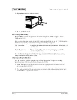
Страница 90: ...edure below If a TM printer is not being used begin with step 3 1 Remove the portion shadowed in the figure below from the printer tray Cut off the two plastic connecting pieces burrs with a cutter or nippers and pull the piece down toward you Bend the part back and forth two or three times so that it can be cut off Pass the cable through the new opening CAUTION If burrs are left after the hatched...

Страница 91: ...able exit by breaking them off with a pair of pliers 3 When setting up the TM printer on the printer tray wrap the cable around the poles on the other side of the tray as shown below to keep it out of the way 4 Slide the printer tray in the direction of the arrow and fit the hooks on the printer tray into the slots in the IR 320 OI R01 001 OI R01 022 ...

Страница 92: ...th one screw 8 Install the TM printer on the printer tray Installing a Printer Dedicated printers are designed especially for the IR systems Any of theses printers can be installed directly on the main body Other types of TM printer can be used on the printer tray described in the previous section Installing a TM Printer The power supply to the printer can be tapped from the TM power connector OI ...

Страница 93: ...he user s guide for that printer Operation progress 1 Attach the printer tray to the IR 320 2 Install the TM printer on the IR 320 3 Confirm the operation of the TM printer 4 The TM printer can be used Refer to the User s Guide of each printer for the instalation and the operation confirmation procedure of the TM printer Installing a Dedicated TM Printer Unit The following dedicated TM Printer uni...

Страница 94: ... Printing out by Windows for printing from the Windows application to the dedicated printer unit Setup procedure Use the following procedure to connect the printer unit 1 Turn on DIP switch 2 7 of the printer unit 2 When connecting a customer display set the baud rate to be the same for the dedicated printer as the customer display by setting their DIP switches Note The customer display and the ba...

Страница 95: ...Rev C Setup 2 57 IR 320 Technical Reference Manual Confidential 4 Bend the cable as shown below 5 Remove the side cover by sliding it downward 6 Remove the two screws as shown below ...

Страница 96: ...isconnect the printer cable for the IR 320 8 Connect the cable for the printer unit and bend it as shown below 9 Slide the printer unit in the direction indicated by the arrows so that the hooked area on the printer unit fits into the groove on the IR 320 Make sure the cable is not hooked by the projection on the plate printer cable ...

Страница 97: ...d the status of the dedicated printer unit Device Tests menu When executing TM print test a test printing is printed to the dedicated printer unit Refer to Device Diagnost ics Utility of Appendix A BIOS Functions for the operating method of the Device Diagnostics Utility Other Operating Confirmation The operation of a dedicated printer unit can be confirmed by using the following procedure instead...

Страница 98: ...2 60 Setup Rev C Confidential Installing a PCI Board The IR 320 has two PCI expansion slots The maximum dimensions of the applicable PCI boards are as follows PCI slots ...

Страница 99: ...body If you do not discharge static electricity trouble could result Touch a grounded metal surface to allow static electricity to discharge Do not touch the connectors Dirt may cause a malfunction Do not apply excessive force to connectors cables and screws during connection Excessive force may damage the connection parts or screw threads 1 Remove the left side cover by sliding it downward 2 Remo...

Страница 100: ...e it pull it all the way out and try again 6 Lock the PCI board with the screws removed in step 4 7 Reattach the side panel with two screws 8 Reattach the side cover When you remove the PCI board be sure to attach a slot cover Installing a Customer Display The following customer displays can be connected to the IR 320 DM D110 DM D210 DM D500 Model name Specification DM D110 210 20 characters x 2 l...

Страница 101: ...20 and start up the Device Diagnostics Utility 3 Confirm that the Customer display is connected correctly and displays correctly by using the Device diagnostics Utility Setup procedure Follow the procedure below to attach a Customer display 1 Pass the cable for the DM D500 through support A and attach support A to the DM D500 When using support B for extension insert the tab on support B into the ...

Страница 102: ...corners of the base are set as shown below 3 Pass the cable for the DM D500 through the base 4 Install the extension on the base Be sure that the projection on the base snaps into the hole in the extension 5 Connect the cable for the DM D500 to the DM connector on the IR 320 ...

Страница 103: ...ble other than the customer display cable such as a telephone line to the connector for the customer display 6 Set the DIP switch so that the baud rate of the customer display is the same as the baud rate of the printer unit The position of the DIP switch should be set as follows Note The customer display and the baud rate of the dedicated printer unit are set to the same speed at the factory ship...

Страница 104: ... bank 1 DSW1 as indicated in the following table 7 Cut off the portion of the customer display cover shown below Cut off the three connecting pieces burrs with a cutter SW1 5 SW1 6 SW1 7 Transfer speed bps ON ON ON 2400 OFF ON ON 4800 ON OFF ON 9600 OFF OFF ON 19200 ON ON OFF 38400 OFF ON OFF 57600 ON OFF OFF 115200 1 SW1 6 SW1 7 SW1 8 Transfer speed bps ON ON ON 2400 OFF ON ON 4800 ON OFF ON 9600...

Страница 105: ...ower On Self Test screen is displayed DM area Confirm the communication speed and the status of the customer display Device Tests menu WhWhen executing the DM display test the test message is displayed in the customer display Refer to Device Diagnostics Utility in Appendix A BIOS Functions about the operation of the Device Ddiagnostics Utiity Installing a Mouse Keyboard A mouse or a keyboard can b...

Страница 106: ...nter unit is not connected the cash drawer cannot be controlled When a dedicated printer is connected connect the cash drawer connector to the drawer connector on the IR 320 When another type of TM printer is connected connect the cash drawer connector to the TM printer drawer connector Note When a non dedicated type TM printer is connected do not connect the cash drawer connector to the drawer co...

Страница 107: ...to do so causes the power plug to heat up and may cause a fire Regularly remove the power plug from the outlet and clean the base of the prongs and between the prongs If you leave the power plug in the outlet for a long time dust may collect on the base of the prongs causing a short and fire Follow these steps to attach the power cable 1 Loosen the screws of the rear cover and remove the rear cove...

Страница 108: ...he default and the power supply is not output Refer to Chapter 1 Jumper Locations and Settings for the jumper setting CAUTION Making a mistake in setting the jumpers can damage the device or cause it to heat up and possibly cause a fire Confirm that the jumper setting is correct before connecting the unit COM5 COM6 Setting COM5 and COM6 cannot used as the default To use The BIOS setting must be ch...

Страница 109: ...COM6 can be used Operating Confirmation Of The Hardware Device Diagnostics Utility Whe using the Device Diagnostics Utility the communication lines between the devices connected with the IR 320 can be tested The Device Diagnostics Utility can test the following The connecting condition of each device The printing test of the TM printer The display test of the customer display The operating test of...

Страница 110: ... in the License agreement check box click NEXT 3 The Location to Save Files dialog is displayed Choose the folder in the installation place and click NEXT C Program Files EPSON Advanced Printer Driver Setup are chosen in the default 4 The file is extracted and the Select OS dialog is displayed Choose your OS in the Select Install OS box Confirm that US is chosen in Select Install Language Click NE...

Страница 111: ...t prints at usual character size EPSON TM T88II R Reduce35 It prints as a reduction in the receipt paper size 3 Click the icon of the printer driver for printing and right click and choose Properties from the menu that is displayed 4 Click the Ports tab and choose COM3 for Print to the following port Click Apply More than one printer driver can be set to the same port 5 Click the General tab and c...

Страница 112: ...pt It prints at usual character size EPSON TM T88II R Reduce35 It prints as a reduction in the receipt paper size Change the printer driver to use by following the steps below 1 Start the system and choose Setting Printer in the start menu 2 The Printers dialog is displayed Confirm thet the icon of the installed printer driver is displayed 3 Click the icon of the printer driver for using to print ...

Страница 113: ...rating Systems can be used for the IR 320 Windows 2000 Professional There is a version preinstalled by EPSON Windows XP Professional Edition Windows 98 SE There is a version preinstalled by EPSON Windows NT Workstation 4 0 SP6a There is a version preinstalled by EPSON MS DOS Ver 6 22 Drivers and Utilities Drivers for using the IR 320 are on the Driver CD ROM included with the IR 320 If the operati...

Страница 114: ...ivers Video Video drivers WINNT Drivers for Windows NT Logon Logon tool Network Network drivers Sound Sound drivers Touch Touch Panel drivers Video Video drivers WIN2K Drivers for Windows2000 Chipset Chipset drivers Dissw Power button prohibited setting tool Epsbatt AC line tool Epserial Serial Driver Logon Logon tool Network Network drivers Sound Sound drivers Touch Touch Panel drivers Video Vide...

Страница 115: ...y 1 The Readme txt file in the root directory contains an overview of this CD ROM and refers to the Readme txt files in the various subdirectories 2 The Readme txt files in the operating system subdirectories explain driver installation un installation for each operating system 3 Readme txt files for KEYCFG OPOS ADK and APDRV are included with the software ...

Страница 116: ... of the W2K label pasted on the product You can set up the Network automatically or set it up later Windows 2000 Service Pack Installation AC line tool Installation When using the Battery Unit OI R03 Change of Double click settings Set up this setting every time a new user starts using Windows 2000 Power button prohibited setting tool Installation Serial Driver Installation Other software Installa...

Страница 117: ... up drive has been formatted to the following file system File system FAT32 Volume label Windows 2000 Pre installed software Microsoft Windows 2000 Professional Microsoft Windows 2000 Service Pack 3 Intel Chipset software installation utility Intel Video driver Intel Network driver Analog Devices Sound driver EPSON Touch Panel driver EPSON Logon tool 1 EPSON DM MS Series setup utility 1 EPSON Powe...

Страница 118: ...pserial EPSON Serial driver backup folder Logon Logon tool backup folder Network Network driver backup folder Sound Sound driver backup folder Touch Touch Panel driver backup folder Video Video driver backup folder Recovery Recovery folder Bootfd Data Bootdisk Folder for files used to create an ordinary boot floppy disk Documents and Settings Folder for saving text and settings I386 Setup file fol...

Страница 119: ...yed Input the product key entered on the cover of the First Step Guide in the COA Certificate of Authenticity package included with this product then click Next 6 The Computer Name and Administrator Password screen is displayed Input the Computer Name and Administrator Password then click Next 7 The Date and Time Settings screen is displayed Set the date and time then click Next 8 The Networking S...

Страница 120: ... Various configurations are executed during the setup procedure and the keyboard and the mouse are automatically set To change their configurations use the control panel Setting the Network A dialog box prompting the user to manually install the network is displayed Set the network settings by the following procedure 1 Open the Control Panel then select Network and Dial up Connections 2 The Networ...

Страница 121: ...or Guest dialog box is displayed Set the settings in accordance with the environment then click Next The explanation here is for the case in which Host is selected 8 The Connection Device dialog box is displayed Set the settings in accordance with the environment then click Next 9 The Allowed Users dialog box is displayed Set the settings in accordance with the environment then click Next 10 The C...

Страница 122: ...e Programs to display a list of the currently installed programs Change Remove will be displayed when EPSON Serial Driver is selected Click Change Remove 3 The Confirm File Deletion dialog box is displayed Click Yes 4 The Remove Programs From Your Computer dialog box is displayed The uninstall process then begins 5 A dialog box is displayed when uninstall is completed Click OK AC line tool AC line...

Страница 123: ...o Windows 3 When setting the registry the following message is displayed Click Yes so Windows is restarted and the setting becomes valid If you click No the setting returns to Windows without becoming valid In this case if you then restart Windows the setting becomes valid Adding Windows 2000 Applications When adding any Windows 2000 application specify the C I386 directory In this directory I386 ...

Страница 124: ...C Support Information Right click the My Computer icon and select Properties from the pull down menu Then the System properties are displayed Click the Support information button so the information on the contact is displayed ...

Страница 125: ...S setting customized note down the BIOS setting value beforehand After the recovery is done you must reset it to that value OS recovery erases all contents of the HDD Back up the necessary data to a floppy disk or other media R R R Recovering ecovering ecovering ecovering method method method method Follow the steps below to carry out OS recovery 1 Turn power to the IR 320 off Turn the main power ...

Страница 126: ...or F _ 13 Select the range to format as the system area on the hard disk Press the 1 key to select 10GB or press the F key to select the full size After that the OS recovery starts 14 The image data exchange dialog will appear Insert the Windows 2000 CD ROM 2 in the CD ROM drive then press the OK button 15 When the prompt below is displayed on the screen OS recovery work is complete X RESTORE _ 16...

Страница 127: ...lume label NTWS40 Pre installed software Microsoft Windows NT Workstation 4 0 Microsoft Windows NT Service Pack 6 Microsoft Internet Explorer 6 00 Service Pack 1 Microsoft Data Access Components 2 0 Service Pack 1 Intel Video driver Intel Network driver Analog Devices Sound driver EPSON Touch Panel driver EPSON Logon tool 1 EPSON DM MS Series setup utility 1 EPSON CD ROM driver for DOS 2 Windows N...

Страница 128: ...ion The root directory of the HDD is structured as follows Backup Keycfg Backup of MSR Utility Win Disk1 Backup of MSR Utility for Windows DOS Backup of MSR Utility for MS DOS Logon Logon tool backup folder Network Network driver backup folder Sound Sound driver backup folder Touch Touch Panel driver backup folder Video Video driver backup folder Ie6sp1 Internet Explorer 6 0 backup folder Mdac MDA...

Страница 129: ...e system and boot the system from the pre installation HDD Windows NT setup will start 2 The Windows NT Setup dialog box is displayed Click Next 3 The License Agreement dialog box is displayed Check the contents then select I accept this agreement and click Next 4 The Name and Organization dialog box is displayed Input the Name and Organization then click Next 5 The Registration dialog box is disp...

Страница 130: ...C Support Information Right click the My Computer icon and select Properties from the pull down menu Then the System properties are displayed Click the Support information button so the information on the contact is displayed ...

Страница 131: ...y onto another medium or drive Example 1 Connect the IR 320 in network to a PC that can write data onto CD Rs 2 Save all data under the C backup recovery data directory of the IR 320 onto the PC 3 Write all data saved in step 2 onto a CD R 4 After saving the data the directory under the C backup recovery directory may be deleted Backing up each driver Each directory under the C backup directory is...

Страница 132: ...nd Windows saved in Preparing a Recovery Medium Restrictions The size of the image data to be saved amounts to 500 600 MB Saving this much data requires a large capacity device such as a CD R MO or server Because of restrictions by EasyRestore the HD image data file HDIMG003 PQI cannot be divided Because EasyRestore runs only on MS DOS it is a requirement of Saving of HD Image Data that MS DOS can...

Страница 133: ...ting a drive in the unused area The start up drive has been formatted to the following file system File system FAT32 Volume label Windows 98 Pre installed software Microsoft Windows 98 Second Edition Intel Chipset software installation utility Intel Video driver Intel Network driver Analog Devices Sound driver EPSON Touch Panel Driver EPSON DM MS Series setup utility 1 EPSON CD ROM driver 2 EPSON ...

Страница 134: ...d installation of Windows 98 Backup Keycfg Backup of MSR Utility Win Disk1 Backup of MSR Utility for Windows DOS Backup of MSR Utility for MS DOS Chipset Backup of Chipset driver Dissw Power button prohibited setting tool backup folder Epsbatt AC line tool backup folder Logon Backup of Logon tool Network Backup of Network Driver Sound Backup of Sound Driver Touch Backup of Touch Panel Driver Video...

Страница 135: ...it product key shown on the COA Certificate of Authenticity Click Next to begin setup If you enter an incorrect key a message is displayed indicating that Select Re enter valid product key and then click Next to return to the Windows Protect Key screen and input the product key again 7 When setup is completed the Congratulations screen is displayed Click Finish 8 The system asks you to set the Dat...

Страница 136: ... or drive Example 1 Connect the IR 320 in network to a PC that can write data onto CD Rs 2 Save all data under the C backup recovery data directory of the IR 320 onto the PC 3 Write all data saved in step 2 onto a CD R 4 After saving the data the directory under the C backup recovery directory may be deleted Backing up each driver Each directory under the C backup directory is the backup of each d...

Страница 137: ...hat the OS recovery starts 6 Following the title EasyRestore the EPSON Logo Startup screen is displayed Select Continue 7 After the OS is recovered set up the OS 8 Return the printer driver for OPOS and Windows saved in Preparing a Recovery Medium Restrictions The size of the image data to be saved amounts to 500 600 MB Saving this much data requires a large capacity device such as a CD R MO or se...

Страница 138: ...Driver from the Driver CD ROM for the IR 320 Other software Installation When using OPOS ADK APD Windows printer drivers and Unimini install the software from the Driver CD ROM for the IR 320 Chipset Driver Installation Install the Chipset Driver from the Driver CD ROM for the IR 320 Network Driver Installation Install the software from the Driver CD ROM for the IR 320 Touch Panel Driver Installat...

Страница 139: ...he Driver CD ROM of IR 320 9 Execute WinXP Video WIN2K_XPE67 EXE in the Driver CD ROM of IR 320 10 The Release note is displayed Click Next 11 The Setup Wizard starts and the Welcome dialog box is displayed Click Next 12 The License Agreement dialog box is displayed Click Yes 13 Installing is completed and the reboot dialog box is displayed Confirm that No I will restart my computer later is selec...

Страница 140: ...M for the IR 320 in the CD ROM drive Start WinXP Chipset infinst_enu EXE 2 The Setup Wizard starts and the Welcome screen is displayed Click Next 3 The License Agreement screen is displayed Click Yes 4 The Readme Information dialog box is displayed Click Next 5 Complete dialog box is displayed Click Finish Uninstalling the Intel chipset driver Uninstalling cannot be done Installing the Network Dri...

Страница 141: ...n dialog box is displayed Input the folder and click Next The default setting is C Program Files EPSON TouchPanel 4 The Hardware Installation dialog box is displayed Click Continue Anyway 5 The Setup Complete dialog box is displayed Confirm that Yes I want to restart my computer now is selected and click Finish to reboot the system Uninstalling the touch panel driver Uninstall the Touch Panel Driv...

Страница 142: ... Deletion dialog box is displayed Click OK Installing the AC AC AC AC l ll line tool ine tool ine tool ine tool This tool is the utility to monitor the switching of the power of the system over to the battery from the AC Line with Windows 2000 when the battery unit OI R03 option is attached For details see page 4 67 Install the AC Line tool using the following procedure 1 Insert the Driver CD ROM ...

Страница 143: ...hipset Driver Installation Install the Chipset Driver from the Driver CD ROM for the IR 320 Network Driver Installation Sound Driver Installation Install the software from the Driver CD ROM for the IR 320 Windows 2000 Service Pack Installation Install the Service Pack from the CD ROM for the Windows 2000 Touch Panel Driver Installation Install the Touch Panel Driver from the CD ROM for the IR 320 ...

Страница 144: ... Wizard starts and the Welcome dialog box is displayed Press Enter 4 The License Agreement is displayed Read it through and confirm your agreement to the terms And then press the F8 key I agree 5 Input the necessary information and continue the installation according to the instructions on the screen 6 When copying of the file is completed reboot the system again according to the instructions on t...

Страница 145: ...ject the Driver CD ROM of IR 320 Insert the CD ROM of Windows 2000 Video Driver Install End 1 The Windows 2000 Setup Wizard starts and the Welcome dialog box is displayed Click Next 2 Input the necessary information and continue the installation according to the instructions on the screen 3 The Your Product Key screen is displayed Input the 25 digit product key shown on the COA Certificate of Auth...

Страница 146: ...ayed Confirm that Yes I want to restart my computer now is selected and click Finish to reboot the system Uninstalling the Intel chipset driver Uninstalling cannot be done Installing the Network Driver This is installed by the exclusive installation program 1 Insert the Driver CD ROM for the IR 320 in the CD ROM drive Start Win2K Network pro2kxpm exe 2 The Setup Wizard starts and the License Agree...

Страница 147: ... in the CD ROM drive Start Win2K Sound SETUP EXE 2 The Setup Wizard starts and the Welcome dialog box is displayed Click Next 3 The Digital Signature Not Found dialog box is displayed Click Yes 4 The reboot dialog box is displayed Confirm that Yes I want to restart my computer now is selected and click Finish to reboot the system Uninstalling the sound driver Uninstall the Sound Driver using the f...

Страница 148: ...rograms to display a list of the currently installed programs Change Remove will be displayed when EPSON Touch Panel Driver is selected Click Change Remove 3 The Confirm File Deletion dialog box is displayed Click Yes 4 The reboot dialog box is displayed Click OK 5 Uninstalling is completed and the dialog box is displayed Click OK Setting the recognition range of the double click When connecting t...

Страница 149: ...he InstallShield Wizard Complete dialog box is displayed Select Yes I want to restart my computer now then click Finish to restart the system Uninstalling the serial port driver Uninstall the serial port driver using the following procedure 1 Open the Control Panel and select Add Remove Programs 2 The Add Remove Programs dialog box is displayed Click Change or Remove Programs to display a list of ...

Страница 150: ...ng is selected Click Change Remove 3 The Confirm File Deletion dialog box is displayed Click OK Power button prohibited setting tool for windows 2000 for windows 2000 for windows 2000 for windows 2000 The Power button prohibited setting tool is the tool setting the registry to prohibit the shift to the shutdown and the stand by mode even if the front power switch is pressed It can prevent the shut...

Страница 151: ...Manual 3 When setting the registry the following message is displayed Click Yes so Windows is restarted and the setting becomes valid When click No the setting returns to Windows without becoming valid In this case if restarting Windows the setting becomes valid ...

Страница 152: ...ng Agreement dialog box is displayed Press the PageDown key and confirm contents to the last page Press the F8 I agree key Operating System Installation Insert the CD ROM for Windows NT and turn on the IR 320 to perform the setup Enter the product key of the COA package You can set up the Network automatically or set it up later Other software Installation When using OPOS ADK APD Windows printer d...

Страница 153: ...ompleted according to the instructions on the screen take the Windows NT CD ROM out of the CD ROM drive and then click Restart Computer to reboot the system The desktop screen of Windows NT is displayed CAUTION Setup is executed with the VGA display Installing the Network Driver This is installed by the exclusive installation program 1 Insert the Driver CD ROM for the IR 320 in the CD ROM drive St...

Страница 154: ...e screen reboot the system CAUTION If the network is installed after the setup an error is caused in the logon procedure After installing the network driver install Service Pack 6a Uninstalling the network driver Uninstalling cannot be done Uninstalling cannot be done Installing Service Pack 6a This is installed by the exclusive installation program 1 Insert the Service Pack 6a CD ROM in the CD RO...

Страница 155: ...x appears Click OK 5 The system reboots Installing the Video Driver Note Before installing the display driver be sure to install Service Pack 6a This is installed by the exclusive installation program 1 Set the Driver CD ROM for the IR 320 to the CD ROM drive Start Winnt Video Winnt4E67 EXE 2 The Release note is displayed Click Next 3 The Setup Wizard starts The Welcome dialog box is displayed Cli...

Страница 156: ...boot the system Uninstalling the sound driver 1 Select Start Menu Settings and open the control panel 2 Select Add Remove Programs in the control panel 3 Select SoundMAX NT 4 Click Add Remove 5 The Confirm File Deletion dialog box is displayed Click Yes 6 Uninstalling is completed and the dialog box is displayed Click OK 7 The reboot dialog box is displayed Click OK 8 Reboot the system Installing ...

Страница 157: ...Menu Settings and open the control panel 2 Select Add Remove Programs in the control panel 3 Select EPSON Touch Panel Driver 4 Click Add Remove 5 The Confirm File Deletion dialog box is displayed Click Yes 6 The reboot dialog box is displayed Click OK 7 Uninstalling is completed and the dialog box is displayed Click OK ...

Страница 158: ...are Installation When using OPOS ADK APD Windows printer drivers and Unimini install the software from the Driver CD ROM for the IR 320 Chipset Driver Installation Install using the Driver CD ROM for the IR 320 Network Driver Installation VIDEO Driver Installation Sound Driver Installation Touch Panel Driver Installation Install the software from the Driver CD ROM for the IR 320 Ultra DMA Setting ...

Страница 159: ... to the instructions on the screen input the necessary items and continue installing 7 When copying of the file is completed take the Setup disk of the MS DOS out of the FDD and then according to the instructions on the screen reboot the system 8 After rebooting the system according to the instructions on the screen set up the Network and the Date Time 9 According to the instructions on the screen...

Страница 160: ...according to the instructions on the screen reboot the system Uninstalling the chipset driver for Intel Uninstalling cannot be done Ultra DMA Setting for the HDD You can set the HDD to the DMA mode by following the steps below 1 Select Start Menu Settings and open the control panel 2 Select System in the control panel 3 The system Properties dialog box appears Click the Device Manager tab 4 Select...

Страница 161: ...to close the System Properties dialog box 10 The following dialog box appears Click Yes to restart the system Installing the Network Driver This is installed by the exclusive installation program 1 Insert the Driver CD ROM for the IR 320 in the CD ROM drive Start Win98 Network PRO98MEM EXE 2 The Setup Wizard starts and the License Agreement dialog box is displayed Select I accept the terms in the ...

Страница 162: ...Add Remove 5 The confirmation dialog box of the uninstalling is displayed Click OK 6 The dialog box to reboot the system is displayed Click Yes to reboot the system Installing the Video Driver This is installed by the exclusive installation program 1 Insert the Driver CD ROM for the IR 320 in the CD ROM drive and start Win98 Video Win9Xe67 EXE 2 The Readme txt dialog box is displayed Click Next 3 ...

Страница 163: ...log box is displayed Select Remove all and click Next 6 The reboot dialog box is displayed Confirm that Yes I want to restart my computer now is selected and click Finish Installing the Touch Panel Driver This is installed by the exclusive installation program 1 Insert the Driver CD ROM for the IR 320 in the CD ROM drive Start Win98 Touch EPSTP9x EXE 2 The Setup Wizard starts and the Welcome dialo...

Страница 164: ... and click Finish to reboot the system Uninstalling the AC line tool Uninstall the AC line tool by the following procedure 1 Select Start Menu Settings and open the control panel 2 Select Add Remove Programs in the control panel 3 Select EPSON AC Line watching 4 Click Add Remove 5 The Confirm File Deletion dialog box is displayed Click OK 6 Reboot the system Power button prohibited setting tool Th...

Страница 165: ...is clicked installation stops and you are returned to Windows 3 When setting the registry the following message is displayed Click Yes so Windows is restarted and the setting becomes valid If you click No the setting returns to Windows without becoming valid In this case when you restart Windows the setting becomes valid ...

Страница 166: ...t a formatted floppy disk in the FDD Touch Panel Driver Installation Install the Touch Panel Driver from the CD ROM for the IR 320 Operating System Installation Insert the MS DOS startup disk and turn on the IR 320 to perform the Setup As for the installation procedure refer to the MS DOS manual CD ROM Driver Installation As for installing MS DOS only the CD ROM drive for the IR 320 is not recogni...

Страница 167: ... drive In case of specifying the other drive name describe the optional drive name C DOS MSCDEX EXE D CDROM L D 8 Restart MS DOS Installing the Network Driver The Network Driver is provided in the form compressed in the Driver CD ROM for the IR 320 MS DOS cannot extract the compressed file Therefore by using another PC to read the CD ROM install the Network driver to the IR 320 after extracting th...

Страница 168: ...y the preceding procedure on the floppy disk 2 Turn on the IR 320 to start MS DOS 3 Insert the floppy disk copied by step 1 in the FDD of the IR 320 4 Copy all files in the floppy disk to the optional directory in the hard disk For example copy it to the C NWCLIENT directory 5 Add the following description to the CONFIG SYS of the MS DOS with a text editor and save it LASTDRIVE Z 6 Edit the follow...

Страница 169: ...EDSTD COM in the Driver CD ROM for the IR 320 to the optional directory in the hard disk For example copy it on C Touch directory Executing Touch Panel Driver Enter the following from the prompt to install the driver medstd Ixx Pxxxx Bxx Fxxxx Dx S The meaning of these parameters are as follows Ixx IRQ number Default 10 Pxxxx Port address Default 2E8 Bxx Baudrate Default 9600 Fxxxx Frequency of Be...

Страница 170: ... The calibration screen is displayed and a mark is displayed in the top left corner of the screen 5 Press the mark s intersection point on the screen The mark will then move to the top center of the screen 6 Hereafter press the mark s intersection point on the screen The mark is thus displayed consecutively in 9 places top left top center top right left center center right center bottom left botto...

Страница 171: ...t if an ordinary user uses the tool Starting the Touch Panel Configuration Tool Start the touch panel environment setting tool by the following procedure 1 Start Windows 2 Select Programs EPSON Touch Panel Tool Touch Panel Configuration Tool in that order from the Start menu 3 The Epson Touch Panel Configuration Tool starts Calibration Function The following screen is displayed if the Calibration ...

Страница 172: ...uthority can use the operation setting function Each item is displayed in gray and cannot be set if an ordinary user uses the tool Default Add a check mark to use the default value for the setting Each setting item in the Custom area is displayed in gray and cannot be changed if Default is checked Remove the check mark from Default to change the settings for each item ...

Страница 173: ...ata are sampled Coordinates Data Sampling Cycle This sets the coordinate data sampling interval within a range of 10 to 155 ms The default setting is 10 The coordinate data sampling interval sets the time coordinate data are sent to the system from the touch panel device On This sets the tap sound On or Off The tap sound is output if this item is checked The default setting is On Frequency This se...

Страница 174: ... by setting the permissible double click recognition range so that it is wider Note When Windows 2000 is set up and a new user is entered set the double click latitude for each user As for the details refer to the Setting the recognition range of the double click section Start the Double Click Latitude Setting by the following procedure Method Execute Programs EPSON Touch Panel Tool Touch Panel Co...

Страница 175: ...y after the right button is specified is recognized as a right click This mode is set as the default 2 Right Fix Mode Taps after the right button is specified are always recognized as right clicks The mode is switched in the right button emulator menu The menu is displayed by tapping the icon on the title bar then the desired mode is selected The set mode is displayed underneath the mouse icon 2 S...

Страница 176: ...d I10 P2E8 B96 S The meaning of these parameters are as follows Ixx IRQ number Default 10 Pxxxx Port address Default 2E8 Bxx Baudrate Default 9600 S Graphic mode You need parameter S Text mode You don t need parameter S 2 The calibration screen is displayed and nine mark is displayed 3 Press the mark in the top left corner of the screen 4 Touch the nine marks on the screen 5 When you finish calibr...

Страница 177: ...the OS Windows XP Professional This is set with the OS Windows 2000 Professional This is set with the OS Windows 98 SE This is set with the OS Windows NT Workstation 4 0 SP6a This is set with the BIOS MS DOS Ver 6 22 This is set with the BIOS Windows XP 1 Select Settings Control Panel Performance and Maintenance Power Options in the Start menu of Windows 2 Power Options Properties is displayed Cli...

Страница 178: ...tion 4 Click OK When there is no HDD access for the time set the HDD Power Down Timer switches over to HDD Power Down and the motor of the HDD stops Windows 2000 Professional 1 Select Settings Control Panel Power Options in the Start menu of Windows 2 Power Options Properties is displayed Click the Power Schemes tab ...

Страница 179: ...e Turn off hard disks option 4 Click OK When there is no HDD access for the time set the HDD Power Down Timer switches over to HDD Power Down and the motor of the HDD stops Windows 98SE 1 Select Settings Control Panel Power Management in the Start menu of Windows 2 Power Management Properties is displayed Click the Power Schemes tab ...

Страница 180: ...s over to HDD Power Down and the motor of the HDD stops Windows NT Workstation 4 0 SP6a Controlling the HDD motor is done through the BIOS For the details see Chapter 5 BIOS Functions MS DOS Ver 6 22 Controlling the HDD motor is done through the BIOS For the details see Chapter 5 BIOS Functions Shift to the HDD power ON When access to HDD occurs the motor of HDD begins to start and the HDD becomes...

Страница 181: ... are used to define the keys for the 28 key keyboard write them into the keyboard firmware and create definition files Utility Utility Utility Utility Utility name Utility name Utility name Utility name OS OS OS OS Page Page Page Page Keyboard firmware setting utility PKMODE32 EXE Windows XP 2000 NT 98 4 10 Keyboard firmware setting utility PKMODE2 EXE MS DOS 4 53 Utility Utility Utility Utility U...

Страница 182: ...Windows XP 2000 NT and Windows 98 4 25 Layer supported 28 key automatic definition utility for Windows PKLDL32 EXE Windows XP 2000 NT and Windows 98 4 39 Layer supported 28 key automatic definition utility for MS DOS PKLDL EXE MS DOS 4 40 Layer switching and reading library LYFUNC DLL PKFUNC DLL Windows XP 2000 NT 4 42 Utility Utility Utility Utility Utility name Utility name Utility name Utility ...

Страница 183: ...ed A Tool for Software Development This tool is the development tool to facilitate the development of POS applications by standardizing the control system of the POS peripheral devices Utility Utility Utility Utility Utility name Utility name Utility name Utility name OS OS OS OS Page Page Page Page Logon Tool Actinkey Logonkey Windows 2000 NT 4 50 Utility Utility Utility Utility OS OS OS OS Page ...

Страница 184: ...reinstalled in the BACKUP KEYCFG DOS folder They can be used by running Setup 28 key definition utility for MS DOS 84 key definition utility for MS DOS Definition data automatic setting utility for MS DOS Layer supported 28 key definition utility These utilities are not preinstalled If you want to use any of these utilities please contact an EPSON dealer Layer supported 28 key automatic definition...

Страница 185: ...e devices is converted into the scan code of the keyboard according to the code conversion table in the keyboard firmware all of which is then handled as keyboard input on the system side The code conversion table has the key definition data for converting the setting values and input data of each device into a scan code which can be rewritten by the utility of each device However the externally c...

Страница 186: ...an be executed as a batch file and for writing it into another system are also provided How to Use Keyboard Firmware Related Utilities Settings for the programming of an external POS keyboard To program an external POS keyboard it is necessary to turm off some of the keyboard firmware functions in order to prevent system malfunction Check the Ignore MSR Keyboard Commands check box in the MSR setti...

Страница 187: ...ne the units you are using for one system Create the definition files k28 kyl and other files of each of the units at this time 2 If you are using an MSR create a definition file pkl file using a text editor 3 Copy each of the definition files onto a floppy disk or other appropriate media 4 Create an appropriate folder in the hard disk of each system and copy the definition files stored on the flo...

Страница 188: ...ayed Specify the destination of the installation directory c Program Files Key Config is the default Click Next MSR Definition file pkl Create this file using a text editor Settings of MSR PKMODE32 EXE Win PKMODE2 EXE DOS Definition of the Key Lock KEYLOCKCFG EXE Win Definition of the 28 keyboard 28KEYCFG EXE Win POSKB28 EXE DOS Definition of the 84 keyboard 84KEYCFG EXE Win POSKB EXE DOS Keyboard...

Страница 189: ...og box is displayed Specify the program folder name Keyboard Config Utilities is the default Click Next 5 The screen for confirming the setting contents is displayed Click Next Installation starts 6 Upon completion of the installation the Setup Complete dialog box is displayed Click Next ...

Страница 190: ... directory by default C Program Files Key Config Start the keyboard firmware utility in either of the following ways Double click PKMODE32 EXE from Windows Explorer Select Keyboard Config Utilities and then MSR Keyboard Configuration Utility from the Program menu Note This program is also contained on the floppy disk packaged with the MSR unit and the 28 key keyboard unit Do not use this floppy di...

Страница 191: ...O JIS1 Track 1 ISO JIS1 Track 2 ISO Track 3 Check the check box of the track to be read More than one track may be specified accordingly Track 1 2 and Track 3 have been selected in the initial setting MSR Code Type English Japanese French German Spanish Selection is made according to the language setting of Windows MSR Start End Sentinels Card Start Card End ISO JIS1 Track 1 Start JIS2 Start JIS2 ...

Страница 192: ...the JIS2 card Also specify a track that can be read by the Keyboard Firm Setting utility for Windows or the PKMODE2 utility Select the 101K B keyboard To have the JIS2 type card read set the end flag to Space Line feed JIS2 End 20 r Key Lock Setting Utility for Windows XP 2000 NT 98 The Key Lock Setting utility sets the function of each position of the key lock Start The Key Lock Setting utility K...

Страница 193: ...ns to call up the desired function quickly Exit Exits the Key Lock Setting utility New Clears the button s function and creates a new setting Load Loads a saved setting Save Saves the current setting Code Opens the KeyCode dialog box Label Opens the KeyLabel dialog box Prog One If you click this button while a key is selected only the code for the selected key is programmed Prog All Programs the s...

Страница 194: ...If you click OK the setting becomes valid and the key dialog box is closed If you click Cancel the setting is canceled If you click Reset the code is cleared Setting the Key Label Use the following steps to set the key label displayed on the key position button 1 Click the key you want to label and it becomes selected 2 If Label is clicked the KeyLabel dialog box is opened 3 Input any characters a...

Страница 195: ...a button is selected Only the selected key is programmed Click Prog All All the keys are programmed If the program ends correctly the following dialog box is displayed Saving the Settings Save the current settings as a file with the following steps 1 If you click Save the Save As dialog box is displayed 2 If you input a file name and click Save the settings are saved in a file Use the file extensi...

Страница 196: ... click Load the Open dialog box is displayed 2 If you select a file name and click Open the selected setting is loaded New To clear the current settings and create new settings click New All the key settings are cleared Exit If you click Exit the key lock setting utility is exited ...

Страница 197: ...se keys cannot be registered alone Concurrent pressing of Ctrl Alt Del Ctrl Esc or Alt Tab cannot be defined Any other key definition utility cannot be programmed together with this utility Do not operate the mouse the touch panel the keyboard or any other inputting device while the program of this utility is being executed Startup The 28 Key Definition utility 28KEYCFG EXE has been copied in the ...

Страница 198: ...lears the button s function and creates a new setting Load Loads a saved setting Save Saves the current setting Code Opens the KeyCode dialog box Label Opens the KeyLabel dialog box Font Opens the Font dialog box Color Opens the Color Specification dialog box Prog One Programs only the code for the selected key when this button is clicked while a key is selected Prog All Programs the settings of a...

Страница 199: ...key if you hold down Shift and click the key immediately to the right of or immediately below the selected key the two keys are connected By repeating this procedure a number of keys can be connected to create one large key If you press Shift while the connected key is selected the connection is canceled 4 If you click OK the setting becomes valid and the key dialog box is closed If you click Canc...

Страница 200: ... as a new line When the Center check box is checked the inputted character is displayed on the key top in the centered position Setting the Key Top Color For setting the key top color use the following procedure 1 Click the key to be set on key top color to make it ready for setting 2 Click Color The Color dialog box is displayed 3 Set the key top color by clicking the color to be set from the col...

Страница 201: ...isplayed on the Custom colors color palette Select the color and click OK 5 When OK is clicked the key is redrawn in the selected color and the Color dialog box is closed When Cancel is clicked the selected color is cancelled Key Program To assign a setting to an actual key run the program by either of the following methods Click Prog One while a button is selected Only the selected key is program...

Страница 202: ...ou input a file name and click Save the settings are saved in a file Use the file extension k28 Loading the Settings Load the settings as follows 1 If you click Load the Open dialog box is displayed 2 If you select a file name and click Open the selected setting is loaded New To clear the current settings and create new settings click New All the key settings are cleared ...

Страница 203: ...means can be defined No means cannot be defined in the table below Definable keys Utility 28KEYCFG EXE OS Windows XP 2000 NT 98 Language Any language Keyboard 101 102 106 series Keys that cannot be defined depending on OS Print Screen Scroll Lock Pause Num Lock Caps Lock Windows Shift Alt Ctrl Menu Ctrl Alt Del Alt Esc Alt Tab Ctrl Esc Limits on key combinations Single Shift Ctrl Alt Esc Yes Yes N...

Страница 204: ...Yes Yes Yes End Yes Yes Yes Yes PageUp Yes Yes Yes Yes PageDown Yes Yes Yes Yes Yes Yes Yes Yes Yes Yes Yes Yes Yes Yes Yes Yes Yes Yes Yes Yes Ten key Yes Yes Yes Yes Ten key Yes No Yes Yes Enter Ten key Yes Yes Yes Yes 0 1 2 3 4 5 6 7 8 9 Ten key Yes No Yes Yes Definable keys continued ...

Страница 205: ...on of the 28 keys in so called layer units and making it possible to define multiple layers 28 keys x number of layers could be defined enabling key input from more than 28 keys This is the layer function There are two methods of switching layers instantaneously Changing layers using the Change Layer Key Shift key type A key is defined in advance for switching to each layer with the specified laye...

Страница 206: ...eys are pressed when any change layer keys are released the layer returned 0 not to change the layer is pressing Under this case when the layer is changed using the software it returned Layer 0 at the same time of other change layer keys are released In the previous 28 key definition utility and 84 key definition key keys are defined with respect to Layer 0 when starting so if a layer other than L...

Страница 207: ...to start installation 2 The Welcome dialog box is displayed Confirm the contents then click the Next button 3 The Choose Destination Location dialog box is displayed Confirm the installation destination folder the click the Next button C Program Files 28 KB Config 4L is set as the default This can be changed if necessary 4 The Select Program Folder dialog box is displayed Confirm the program folde...

Страница 208: ...estart my computer now and click the Finish button to restart the windows Windows 98 7 The Setup Complete dialog box is displayed Click the Finish button to end the installation Uninstall Procedure Uninstall this utility by the following procedure 1 Open the Control Panel 2 Double click on Add Remove Programs 3 Click the Install Remove tab then select 28K B Config Utilities 4 Layers Supported for ...

Страница 209: ...Rev C Utilities 4 29 IR 320 Technical Reference Manual Windows XP 2000 NT Windows 98 4 Click the Add Remove button 5 The Confirm File Deletion dialog box is displayed Click the Yes button ...

Страница 210: ... the shared files click the Yes button 8 The following dialog box is displayed and the uninstall process is completed Click the OK button Setting the Utility Layer 28 key Definition Utility The Layer 28 key Definition Utility can define the keys of the 28 key keyboard unit in Windows Setting of codes for the 28 key keyboard can be done for layers 0 3 a total of 4 layers Notes Be careful of the fol...

Страница 211: ...tem so these keys cannot be registered independently The Ctrl Alt Del Ctrl Esc Alt Esc and Alt Tab keys pressed simultaneously cannot be defined This utility cannot be run simultaneously with other key definition utilities such as 28keycfg exe Do not operate the mouse touch panel keyboard or other input device while this utility program is running while definition data are being written The file e...

Страница 212: ...Config Utilities 4L 28 KB Config Utility 4 Layers Supported in the Programs menu The following starting screen is displayed when the program starts Speed Buttons The speed buttons configured from 13 buttons are displayed under the title bar Clicking these speed buttons enables the desired function to be called up immediately Exit Closes the utility New Clears the button s setting and creates a new...

Страница 213: ...sponds to an actual key top on the keyboard unit Key tops are defined by the following procedure 1 Select the key which you would like to set the code for Clicking it once more cancels the selection 2 The Code dialog box opens when the Code button is clicked 3 Select the list box with the layer name where the key code is to be set by clicking it with the mouse 4 Input the code to be set for the se...

Страница 214: ...keys by the following procedure 1 Click the Option button to open the Option dialog box 2 The change layer keys for each respective layer 1 to 3 can be set in the 3 drop down lists in the dialog box Select the number of the key that is to be used as the change layer key from the drop down list The change layer key is not set if is selected Note The key set as the change layer key cannot be used fo...

Страница 215: ...arranged around the center of the keytop Setting the Keytop Color Set the keytop color by the following procedure 1 Select the key that the color is to be set for and activate it 2 Clicking the Color button displays the color dialog box 3 Set the keytop color Select the color to be se from the color palette 4 Clicking the OK button causes the key to be redrawn in the selected color and closes the ...

Страница 216: ...he selected font Programming Keys To assign settings to the actual keys it is necessary to program them Program the keys by either of the following methods While a key is in the selected state click the Prog One button Only the selected key is programmed Click the Prog All button All the keys are programmed The following dialog box is displayed if the programming ends normally ...

Страница 217: ... same name as the specified file already exists Clicking the Yes button overwrites the existing file Clicking the No button cancels the save operation Notes If the Exit New or Load button is clicked while the settings are changed but have not been saved the dialog boxes shown below are displayed and confirmation of whether or not to save the current settings is requested Clicking the Yes button op...

Страница 218: ...settings by the following procedure 1 Clicking the Load button displays the Open File dialog box 2 Select the file name then click the Open button to read the selected settings Creating New Settings Click the New button to clear the settings used up to the present and set new settings All the key settings are cleared ...

Страница 219: ...ose Clicking the Exit button closes the Layer 28 Definition Utility Layer 28 key Auto Definition Utility for Windows Function This utility loads definition files created by the Layer 28 Keyboard Definition Utility It is used for batch processing etc Starting The Layer 28 key Auto Definition Utility for Windows PKLDL32 EXE is copied to the directory specified during installation The utility is copi...

Страница 220: ...ogramming with 28keyCfg or other key definition utility The keyboard and mouse do not respond during reading or writing of the settings As much as possible do not perform any operations that would generate an interrupt such as tapping the touch panel during reading or writing of the settings The Layer 28 key Auto Definition Utility for MS DOS Outline This is a MS DOS utility that loads definition ...

Страница 221: ...will occur if these are operated during data communications and it may stop running normally Do not press Reset or turn the power off while this utility is running Messages Message Content EPSON Layer Keyboard Auto Definition Utility Vx xx xx When started Usage PKLDL data file data file definition data file L28 Layer 28Key definition data Usage EPSON Layer Keyboard Auto Definition Utility Vx xx xx...

Страница 222: ...cted layer No 20 Communications error 21 Opening error Notes Copy LYFUNC DLL and PKFUNC DLL to the same folder as the application program This library cannot be used during programming with 28keyCfg etc The keyboard and mouse do not respond during reading or writing of the settings Do not perform any operations that would generate an interrupt such as tapping the touch panel during reading or writ...

Страница 223: ...tion utility is stored in the following directory on the hard disk C Program Files Key Config 84keycfg exe You can start the 84 key configuration utility by double clicking this file in Windows Explorer or by selecting Program Key Configuration Utilities Configure 84 Keyboard from the menu When the program starts the following screen is displayed ...

Страница 224: ...s a new setting Load Loads a saved setting Save Saves the current setting Label Opens the key label dialog box Code Opens the key code dialog box Color Opens the color dialog Prog One If you click this button while another button is selected the utility programs only the key for the selected button Prog All The utility programs settings of all the buttons View Opens the key view window and display...

Страница 225: ...By repeating this procedure a number of keys can be connected to create one large key If you press the Shift key while the connected key is selected the connection is canceled 4 If you click the OK button the setting is made and the key code dialog is closed If you click the Cancel button the setting is canceled If you click the Reset button the code is cleared Setting the Key Label Use the follow...

Страница 226: ...methods Click the Prog One button while the button is selected Only the selected key is programmed Click the Prog All button All the keys are programmed If the program ends correctly the following is displayed Saving the Settings You can save the current settings as a file using the following procedure 1 Click the Save button and the Save As dialog is displayed This is the standard Windows functio...

Страница 227: ...You can change the size of the key view window by dragging one of its corners You can close the window by clicking the x button at the right end of the title bar Printing the Settings To print the current settings use the following steps 1 Click the Print button to display the print dialog This is the standard Windows function For details see the Windows manual 2 If you click OK the settings are p...

Страница 228: ...ile for specifying the 28 key keyboard key lock setting file for Windows or the setting file for this utility k28 kyl file n When the n option is specified the following dialog box is displayed at the time of termination While the setting is being transferred the dialog box indicating the situation is displayed While the 28 key keyboard key lock setting file is being transferred the following is d...

Страница 229: ...n02 32 0A Ctrl CardStart CS CardEnd CE Track1Start 1S Track1End 1E Track2Start 2S Track2End 2E Track3Start 3S Track3End 3E JIS2Start JS JIS2End JE In the General section an entry line that may affect the entirety is described in principle IgnoreCommands may be specified to be On When it is specified to be On the setting of the keyboard or MSR cannot be read or written SystemParamxx is described wh...

Страница 230: ...be described in more than one file For xx specify the decimal in order from 00 up to 99 CardStart CadEnd Track1Start Track1End Track2Start Track2End Track3Start Track3End JIS2Start and JIS2End are SSs ESs for reading the MSR Normal characters including space can be described as they are Special characters can be described as xx where xx is a two digit hexadecimal Specifically line feed tab and bac...

Страница 231: ...After installation of the SEGina in Windows NT 4 0 and Windows 2000 be sure to reboot the system If the Actinkey is executed without rebooting the system trouble may occur If trouble occurs reinstall the SEGina How to Use The following three modules are installed SEGina Controls logon with its main module Logonkey Software keyboard displayed at the time of logon Actinkey Software keyboard displaye...

Страница 232: ...r such as graphics video and sound a user friendly GUI and multitasking For information on the installation procedure for the OPOS ADK see the user s guide registered in the C Backup Oposadk directory Creating the Component Software The POS device needs a control program The device control object once existed as a part of monolithic POS application software Because of this monolithic structure POS...

Страница 233: ... U950 SO would have to be replaced by a TM U375 SO but the rest of the software including the POS printer CO would remain the same In other words a switch from one printer to another requires only a change in the SO EPSON Software The software products OCX drivers that EPSON offers to enable such an OPOS system are called the EPSON OPOS ADK The EPSON OPOS ADK provides the OCX driver and much more ...

Страница 234: ...ck decodes for Track 1 Track 2 and Track 3 Sets the DM MR123 when it is selected US Responds with the MSR data in the scan code of the English 101 key keyboard default value JP Responds with the MSR data in the scan decode of the Japanese 106 key keyboard FR Responds with the MSR data in the scan decode of the French 106 key keyboard GR Responds with the MSR data in the scan decode of the German 1...

Страница 235: ...buzzer sounds once When an error is caused to the magnetic card reading the buzzer sounds three times The LED lights up at the same time BEEP OFF Invalidates the sound loaded from the card with the MSR123 and only illuminates the LED MSR m Specifies the track that enables the MSR decode The following four characters can be specified 1 ISO JIS1 type Track 1 2 ISO JIS1 type Track 2 3 ISO JIS1 type T...

Страница 236: ...e This utility is started from and executed on MS DOS It cannot be executed from the DOS box This utility uses the K B interface for communication with the firmware For this reason do not operate the 28 key keyboard the KeyLock and the MSR as well as the external keyboard during the execution or an error is caused during the data communication and this utility cannot start in order Do not reset th...

Страница 237: ...SS Track Start Sentinel string TK ES Track End Sentinel string TKJSS JIS2 Start Sentinel string TKJES JIS2 End Sentinel string BEEP ON MSR Beep ON BEEP OFF MSR Beep OFF MSR m MSR track m KEYTBL Set KeyTable TRACE TRON TROFF See VAL Set Addr VAL xxh yyh PARA CODE DATA Parameter Dump ADDR 0 1 2 3 4 5 6 7 8 9 A B C D E F 0123456789ABCDEF 0000 00 01 02 03 04 05 06 07 08 09 0A 0B 0C 0D 0E 0F 0010 30 31...

Страница 238: ...utility for MS DOS POSKB28 EXE is copied into the specified directory If no directory is specified the utility is copied into the C POSKB directory Start this program as follows 1 Exit Windows and restart the system in DOS mode 2 At the DOS prompt type POSKB28 and press Enter POS key error messages Message Description Firmware version is not correct Firmware version error and others Invalid parame...

Страница 239: ...eys are displayed on the screen in the same array as the keyboard unit Select the key to be edited with the and keys and press Enter to start the editing 2 Press the keys one by one according to the contents of the key to be defined The key definition contents are displayed in order of inputting in the New column in the lower part of the screen The previous key definition contents are displayed in...

Страница 240: ...key definition data when this utility is finished List of Definable Keys Following is a list of definable keys with the supplied utilities Yes means can be defined No means cannot be defined in the table below Definable keys Utility POSKB28 EXE OS DOS Language U S mode Keyboard 101 series Keys that cannot be defined depending on OS Print Screen Scroll Lock Pause Num Lock Caps Lock Ctrl Alt Del Shi...

Страница 241: ... No Yes Yes Enter Ten key Yes No Yes Yes 0 1 2 3 4 5 6 7 8 9 Ten key Yes No Yes No Thecompatibilityofthe84 KeyConfigurationUtility forMS DOS andthekeyboardfirmware Keyboard firmware 3 00 3 03 POSKB exe Ver 2 11 OK OK POSKB exe Ver 2 00 OK NG Key definitions Number of definitions 84 keys and 6 position key lock keys 16 or 21 characters maximum per key Shift Ctrl Alt Gray are each handled as one cha...

Страница 242: ...nd buttons below File Names the file Key definitions are saved or loaded using the file name created with this function Load Loads the key definition data file you specify Save Writes key definition data to the disk file named by the file function Edit Edits key definitions one key at a time Download Writes the key definition data to the keyboard memory The keyboard data does not change until the ...

Страница 243: ...o confirm the file name or ESC to cancel When you exit this utility the file name defined by the File command is saved in the KBD_DL CFG file When the utility is booted up next the name of the file containing the key definition data is read from KBD_DL CFG Load Command When you select the Load command the following screen is displayed Press Enter to read the key definition data from the file creat...

Страница 244: ...tilities Rev C Press Enter to save the key definition data to the file created by the File command Edit Command When you select Edit the following screen is displayed Press Enter to switch to the screen below ...

Страница 245: ...the key lock keys Enter the definition for the selected key Your definition is displayed in the New row Use the definition keys below to edit the key definitions Alt Ctrl Delete the previous key definition Shift Shift Delete input data and revert to the definition before the key was selected Ctrl Shift Save the input data The keytop changes to show that the key has been defined Press ESC to quit t...

Страница 246: ... Quit the following screen is displayed Press Enter to quit this program You can also exit the program by pressing the ESC key but when you press ESC the file name created with the File command is not saved Error Messages The program displays the following error messages During boot up Invalid key configuration format Press any key to continue A data inconsistency exists in the key conversion file...

Страница 247: ...city on the hard disk drive Download command Key map download Fail Time Out Press any key to continue Could not write the key definition data to the keyboard Upload command Key map upload Fail Time Out Press any key to continue Could not read the key definition data to the keyboard Automatic Definition Data Setting Utility For MS DOS Outline This utility automatically sets the definition informati...

Страница 248: ...n Utility Vx xx xx During startup Usage PKLOAD data file data file definition data file K84 84Key definition data K28 28Key definition data KYL KeyLock definition data PKUPLD saved data FLD PKUPLD2 saved data PKL PKMODE definition data Usage EPSON POS Keyboard Auto Definition Utility Vx xx xx Now transfer 28Key Definition data 28 key definition data transfer EPSON POS Keyboard Auto Definition Util...

Страница 249: ... Parameter error abnormal termination 14 Error in communication with the firmware abnormal termination 20 Error during file access abnormal termination 21 Abnormal file data format abnormal termination File format Section Entry Parameter underlined parameters are the default values Remarks General Fixed value Be sure to describe at the start Version PKL100 Fixed value Be sure to describe at the st...

Страница 250: ...de Input Enabled Characters are characters and can be input Input the hexadecimal as nn within a range from 01h to 7Fh Effective up to 7 characters The 8th character and those thereafter are neglected Because even the line feed character is effective do not carelessly input a space or a tab CardEnd Track1Start Track1End Track2Start Track2End Track3Start Track3End JIS2Start JIS2End CodeDefinition00...

Страница 251: ...ith the Alt key List of key numbers keys shaded in gray cannot be set Power Management Driver APM2 0 When this driver is installed the following power management functions become available Turning off the power to the system after shutting down Windows NT Notification that the front power switch was pressed Notification that the AC power is abnormal The Power Management Driver APM2 0 is attached t...

Страница 252: ... is extracted into the specified directory 5 After the extraction the Termination dialog box is displayed Click OK to close the Termination dialog box 6 The following Setup screen is displayed 7 Confirm the directory into which the driver should be installed and click Setup To change the directory click Change Directory and specify the destination of the installation directory 8 When Setup is clic...

Страница 253: ...ou to reboot Click Restart Now and reboot the OS The driver becomes available after rebooting Confirmation After rebooting the OS check whether the driver has been installed properly by using the following procedure 1 Confirm that the power plug icon is displayed on the task bar ...

Страница 254: ...ble clicked the following setting screen is displayed Click OK without changing the setting to exit the setting screen To conceal the power plug icon on the task bar select the Settings tab on the above setting screen uncheck the Show Icon in Taskbar check box and click OK The power plug icon disappears from the task bar ...

Страница 255: ...WinNT Shutdown By using the WM_POWERBROADCAST notification from the driver the processing can be performed from the normal shutdown of Windows NT to the power off The following shows easy sample codes In practical operation the shutdown should be performed after terminating all applications LRESULT CALLBACK WndProc HWND hWnd UINT Message WPARAM wParam LPARAM lParam HWND hTmpWnd HBRUSH hTmpBrush HA...

Страница 256: ...s below for the installation 1 Execute C backup epsbatt Epsbatt exe The Welcome dialog appears Click Next 2 When the installation is finished the Reboot dialog appears Select Yes I want to restart my computer now and click Finish 3 The system is rebooted and the tool is automatically started Uninstallation Follow the steps below for uninstallation 1 Open Control Panel 2 Select Add Remove Applicati...

Страница 257: ...Rev C Utilities 4 77 IR 320 Technical Reference Manual Exit Right click the icon on the task tray and select Exit from the pop up menu to exit the tool ...

Страница 258: ...he settings are cleared Therefore be sure to set the settings after updating it Usage 1 Execute C backup dissw DISSW EXE 2 The following message appears Click Yes 3 When the registery is set the following message appears Clicking Yes reboots Windows and the settings are available Clicking No returns to Windows without the settings being available In this case if you reboot Windows the settings are...

Страница 259: ...ocedure Check to ascertain that reading and writing is not being performed on the compact flash before detaching it 1 Perform a left hand click on the icon in the task bar and then click on Change device in Swappabe Bay 2 The following dialog box will be displayed Attach or detach the card at this point 3 Click on the OK button once the card has been attached or detached ...

Страница 260: ...4 80 Utilities Rev C ...

Страница 261: ...tails HDD Power Down Timer Setting The HDD Power Down Timer settings are made through the OS in Windows XP 2000 98 but in Windows NT 95 and DOS the settings are made through the BIOS as detailed below To have the HDD motor stop when the HDD is not accessed for a certain time follow the steps below 1 Start up the BIOS Setup Utility 2 Select Power Management Setup 3 Select HDD Power Down 4 Select th...

Страница 262: ...le your changes for a new configuration and to exit the BIOS setup utility 1 Display the BIOS setup main menu 2 Select Save Exit Setup and press Enter 3 The message SAVE to CMOS and EXIT Y N is displayed Press Y and Enter in this order to exit the BIOS setup utility validate the changed settings and reboot the system Follow the procedure below to cancel changes and exit the BIOS setup utility 1 Di...

Страница 263: ...p utility save exit and then restart the system When the BIOS Setup utility cannot be started up clear the CMOS with the jamper Clear the CMOS by shorting 2 3 of JP5 For details see Chapter 1 Jumper Locations and Settings Changing settings To choose an item first move the cursor onto a desired field with the arrow keys Next select a value in the field with PageUp or PageDown Finally select the Sav...

Страница 264: ...n can be made Load Fail Safe Defaults The load fail Safe defaults are executed when the minimum preset prescribed values required for the startup are set for each item This function is only provided for troubleshooting and is normally not used Load Optimized Defaults The load optimized defaults are executed when preset prescribed values are set for each item so that the system operates under optim...

Страница 265: ... information set by the user is applied Access Mode Set the access Method to the connected device Note that when the device detection method is set as None it cannot be changed CHS Access for the device is shortened with Cylinder Head Sector Addressing having 0 to 1023 cylinders 0 to 15 heads and 0 to 63 sectors LBA Shortened with the Logical Block Addressing Method the entire memory area is divid...

Страница 266: ...em resources when using this setting select Disabled under Integrated Peripherals Onboard FDC Controller and Yes under Advanced BIOS Features Report No FDD For WIN 95 When using this setting or the Disabled setting for the FDC be sure to change to the Halt On setting 360K 5 25 in A 5 25 inch drive cannot be loaded on this device so 5 25 cannot be selected as a setting 1 2M 5 25 in A 5 25 inch driv...

Страница 267: ...auto detection of the IDE device is not omitted Quick Power On Self Test Sets POST processing conditions The default setting Quick Power On Self Test is set as Enabled Enabled This setting is used to execute the POST processing memory self diagnostic test only once during startup This setting can be used to reduce the time required for startup Disabled This setting is used to execute the POST proc...

Страница 268: ...ed This setting is used when the apparatus is to be used at a fixed setting without changing the number of repetitions or the intervals between repetitions For the fixed setting a repetition occurs once every 6 seconds with intervals of 250 msec This is the normal setting Enabled This setting is used when the number of repetitions and the intervals between repetitions is changed For details refer ...

Страница 269: ... The default setting is No No No is the setting used when no communication is made to the OS This is the normal setting Yes This setting is used when an FDD is not installed or when the necessary software has not been installed More exactly this setting is used to communicate to the OS that the IRQ 6 used by the FDC has been opened Please refer to the section on floppy disks regarding the use of F...

Страница 270: ... Hub The default setting is Disabled The normal setting is Disabled Delayed Transaction Always set this to Enabled CAS Latency This setting sets the number of clocks for the video cache memory CAS waiting period the amount of time required after the address is specified until the data can be read out There are 2 options a setting of 2 or 3 The default setting is 3 The normal setting is 3 to ensure...

Страница 271: ...r the connection device is determined as BIOS If any of the devices connected does not support DMA mode the maximum mode that device supports will be set If On Chip Primary Secondary PCI IDE is set to Disabled the corresponding items cannot be changed When using the UDMA set as Auto The transfer mode for the DMA mode compatible device connected to the IDE interface in each OS can be changed to the...

Страница 272: ... 1 2 3 4 This setting enables disables serial controller 1 2 3 4 combination of the I O address and IRQ resource for serial port 1 inside the S I O W83627 The default setting are as follows Serial Port 1 3F8 IRQ4 Serial Port 2 2F8 IRQ3 Serial Port 3 3E8 IRQ11 Serial Port 4 2E8 IRQ10 There are options the 3F8 IRQ4 setting 2F8 IRQ3 setting 3E8 IRQ4 setting 2E8 IRQ3 setting 3F8 IRQ11 setting 2F8 IRQ1...

Страница 273: ...nfiguration Table 5 5 Power Management Setup menu Items Description Video Off Method Sets the method to turn the monitor off for the Video Off Mode The default setting is DPMS Change the setting to match the system configuration type of connected monitor The settings are explained below Bland Screen Use this setting when connecting an earlier version monitor that is compatible with power managemen...

Страница 274: ...button is pressed and held for at least 4 seconds 1 Shift to the Suspend mode once and the power supply is forcefully turned off after 4 seconds Disabled 1 Nothing happens when the Power button is pressed in the Full On mode 2 Recover to the Full On mode when the Power button is pressed in the Suspend mode 3 If the Power button is pressed and held for at least 4 seconds the power supply is forcefu...

Страница 275: ...riate date Use Time hh mm ss Alarm to set the appropriate time Once the setting is made the power turns on or the system resumes to Full On Mode on the selected day and time each month Date of Month Alarm Time hh mm ss Alarm System Battery Sets the system battery is equipped not equipped The default is Not Equipped There are two options Not Equipped and Equipped Reload Global Timer Events Sets the...

Страница 276: ... with BIOS version 2 13 00 or higher If your BIOS version is before 2 12 upgrade the BIOS and then do the above procedure When access to HDD occurs the motor of HDD begins to start and the HDD becomes accessible Windows 98 2000 XP Windows 98 and later operating systems have a hard disk drive power down function Therefore this function can be used to control hard disk drive power down in these oper...

Страница 277: ... reserved static allocation and are not affected by the PnP BIOS automatic dynamic allocation When making changes be careful not to create a resource conflict DMA Resources Sets the handling of DMA resources DMA channels You can change DMA Resources 0 1 3 5 6 and 7 The default setting is PCI ISA PnP for each resource PCI ISA PnP The target DMA resources are allocated automatically dynamic allocati...

Страница 278: ...ek Day of the week Automatically determined by the settings of Year Month and Day Month Jan Feb Mar Apr May Jun Jul Aug Sep Oct Nov Dec Year Month Day Selected from the options Last day of the current month Either 28 30 or 31 is automatically determined according to the specified month When the year is a leap year the last day of February will automatically be 29 Hour Minute Second Selected from t...

Страница 279: ...the device The LBA method is normally used Capacity This item indicates the memory capacity for the connection device The following differences occur depending on the device detection method used Auto The value calculated according to information obtained by the device is displayed Manual The value calculated according to information specified by the user is displayed Cylinder This item indicates ...

Страница 280: ...en the access method is set as CHS When connecting a device for which there is no particular value specified the number 1 is specified as the maximum number of cylinders Sector This item indicates the number of sectors for the connection device The following differences will occur depending on the device detection method used Auto The value obtained by the device is displayed Manual The user can s...

Страница 281: ...d Quick Post Disabled Enabled Disabled Disabled Quick Power On Self Test Disabled Enabled Enabled Enabled First Boot Device Floppy LS120 HDD 0 SCSI CDROM HDD 1 HDD 2 HDD 3 ZIP100 LAN Disabled Floppy Floppy Second Boot Device Floppy LS120 HDD 0 SCSI CDROM HDD 1 HDD 2 HDD 3 ZIP100 LAN Disabled HDD 0 HDD 0 Third Boot Device Floppy LS120 HDD 0 SCSI CDROM HDD 1 HDD 2 HDD 3 ZIP100 LAN Disabled SCSI SCSI...

Страница 282: ...elay Msec 250 500 750 1000 250 250 Security Option Setup System Setup Setup OS Select For DRAM 64MB Non OS2 OS2 Non OS2 Non OS2 HDD S M A R T Capability Disabled Enabled Enabled Enabled Report No FDD For WIN 95 No Yes No No C8000 CBFFF Shadow Disabled Enabled Disabled Disabled CC000 CFFFF Shadow Disabled Enabled Disabled Disabled D0000 D3FFF Shadow Disabled Enabled Disabled Disabled D4000 D7FFF Sh...

Страница 283: ...ed Disabled Disabled CPU Latency Timer Disabled Enabled Disabled Disabled Delayed Transaction Disabled Enabled Enabled Enabled CAS Latency 3 2 3 3 Paging Mode Control Close Open Open Open RAS to CAS Override by CAS LT Override 2 by CAS LT by CAS LT RAS Timing Slow Fast Fast Fast RAS Precharge Timing Slow Fast Fast Fast Item Options Fail Safe Default Optimized Default On Chip Primary PCI IDE Disabl...

Страница 284: ...bled Auto Auto Auto IDE Primary Slave UDMA Disabled Auto Auto Auto IDE Secondary Master UDMA Disabled Auto Auto Auto IDE Secondary Slave UDMA Disabled Auto Auto Auto USB Controller Disabled Enabled Enabled Enabled USB Keyboard Support Disabled Enabled Disabled Disabled AC97 Audio Auto Disabled Auto Auto Onboard LAN Device Disabled Enabled Enabled Enabled Item Options Fail Safe Default Optimized De...

Страница 285: ...Q4 2E8 IRQ3 3F8 IRQ11 2F8 IRQ10 3E8 IRQ11 2E8 IRQ10 338 IRQ11 238 IRQ10 3F8 IRQ4 3F8 IRQ4 Onboard Serial Port 2 Disabled 3F8 IRQ4 2F8 IRQ3 3E8 IRQ4 2E8 IRQ3 3F8 IRQ11 2F8 IRQ10 3E8 IRQ11 2E8 IRQ10 338 IRQ11 238 IRQ10 2F8 IRQ3 2F8 IRQ3 Onboard Serial Port 3 Disabled 3F8 IRQ4 2F8 IRQ3 3E8 IRQ4 2E8 IRQ3 3F8 IRQ11 2F8 IRQ10 3E8 IRQ11 2E8 IRQ10 338 IRQ11 238 IRQ10 3E8 IRQ11 3E8 IRQ11 Onboard Serial Por...

Страница 286: ... set as EPP or as ECP EPP the user can then perform the necessary settings When the Parallel Port Mode for the ECP Mode Use DMA is set as ECP or as ECP EPP the user can then perform the necessary settings Item Options Fail Safe Default Optimized Default Onboard Serial Port 5 Disabled 3F8 2F8 3E8 2E8 338 238 Disabled Disabled Serial Port 5 Use IRQ IRQ3 IRQ4 IRQ5 IRQ7 IRQ10 IRQ11 IRQ14 IRQ15 IRQ7 IR...

Страница 287: ...creen V H SYNC Blank DPMS Blank Screen DPMS Video Off In Suspend No Yes Yes Yes Suspend Type Stop Grant PwrOn Suspend PwrOn Suspend PwrOn Suspend MODEM Use IRQ NA 3 4 5 7 10 11 14 15 3 NA Suspend Mode Disabled 1Min 2Min 4Min 8Min 12Min 20Min 30Min 40Min 1 Hour Disabled Disabled HDD Power Down Disabled 1 Min 2 Min 3 Min 4 Min 5 Min 6 Min 7 Min 8 Min 9 Min 10 Min 11 Min 12 Min 13 Min 14 Min 15 Min D...

Страница 288: ...g Disabled Enabled Disabled Disabled Resume by Alarm Disabled Enabled Disabled Disabled Date of Month Alarm Time hh mm ss Alarm Primary IDE 0 Disabled Enabled Enabled Enabled Primary IDE 1 Disabled Enabled Disabled Disabled Secondary IDE 0 Disabled Enabled Disabled Disabled Secondary IDE 1 Disabled Enabled Disabled Disabled FDD COM LPT Port Disabled Enabled Disabled Enabled PCI PIRQ A D Disabled E...

Страница 289: ...nP PCI ISA PnP IRQ 7 assigned to PCI ISA PnP Legacy ISA PCI ISA PnP PCI ISA PnP IRQ 9 assigned to PCI ISA PnP Legacy ISA PCI ISA PnP PCI ISA PnP IRQ 10 assigned to PCI ISA PnP Legacy ISA PCI ISA PnP PCI ISA PnP IRQ 11 assigned to PCI ISA PnP Legacy ISA PCI ISA PnP PCI ISA PnP IRQ 12 assigned to PCI ISA PnP Legacy ISA PCI ISA PnP PCI ISA PnP IRQ 14 assigned to PCI ISA PnP Legacy ISA PCI ISA PnP PCI...

Страница 290: ...ings screen For Reserved Memory Base N A and D000 can be selected from the option settings For Reserved Memory Size 64K is the only option setting that can be selected Item Options Fail Safe Default Optimized Default Reserved Memory Base N A D000 N A N A Reserved Memory Length 64K 64K 64K PCI VGA Palette Snoop Disabled Enabled Disabled Disabled ...

Страница 291: ...fter you press Enter the message below is displayed CONFIRM PASSWORD Retype the password you typed If you do not want to use any password simply press Enter at both prompts The password will be cleared and the password function will be disabled If you forget your password short pins 2 and 3 of jumper JP5 for IR 320 and turn on the power to clear the contents of the CMOS After clearing the CMOS be ...

Страница 292: ...ry of the main board CMOS checksum error Defaults loaded The Checksum of the CMOS is incorrect so the system loads the default equipment configuration A checksum error may indicate that the COMS is corrupt This error may be caused by a weak battery Check the lithium battery and replace it if necessary DISK BOOT FAILURE INSERT SYSTEM DISK AND PRESS ENTER When the disk that the system file is not in...

Страница 293: ...according to the message So another processing is done Table 5 9 POST processing messages Message Description Press DEL to enter SETUP ESC to skip memory test Press DEL to enter SETUP This message is displayed in the lower left of the screen Press ESC to omit the full memory test Press DEL to start POST again Press F10 to run device diagnostics program Press F10 to boot the device diagnostics util...

Страница 294: ...5 34 BIOS Functions Rev C ...

Страница 295: ...sfied self diagnosis for each device cannot be performed Table 6 1 Conditions Setting Condition Connection to the TM printer The TM printer needs to be connected to the IR 320 body Even if you will not test the TM printer connect the TM printer to either the COM port or LPT1 Setting of the TM printer DIP switches Set the receive buffer to the maximum Set the selection switch connection non connect...

Страница 296: ... Set the communication settings of the customer display following the instructions below Baud rate 9600 bps Word length 8 bits Parity None For the setup procedure see the instruction manual for the TM display Connection of the cash drawer To check the kick back motion of the drawer connect the cash drawer Connection of the loop back connector To execute the loop back test for the serial ports and ...

Страница 297: ...agnostics utility is closed and the IR 320 is reset Initialize When you select Initialize from the menu bar the device self diagnostic utility is initialized If the TM status message column in the TM Drawer area or the DM status message column in the DM area shows No communication remove the cause and select Initialize to initialize the program Screen Layout When the device diagnostic utility star...

Страница 298: ...gnal Indicates the signal and signal definition this product is using to reset the TM printer You see None here because this printer does not have a reset signal Baud rate Indicates the baud rate that device diagnostics is using to communicate with the TM printer and DM display Word length Indicates the word length that device diagnostics is using to communicate with the TM printer Parity Indicate...

Страница 299: ... printer correctly Before connecting the cables be sure to power off the IR 320 Is the printer s power switch on Is the TM printer connected to the port selected at startup of the device self diagnostic utility Is the self test for the TM printer not executed at start up of the device self diagnostic utility Do not execute the self test Is the paper FEED switch not pressed at start up of the devic...

Страница 300: ...ndicates DM status See the table below Table 6 5 DM status messages Message Description Disable COM port A is not set at 3F8h Set COM port A to 3F8h in setup No communication The device self diagnostic utility cannot communicate with the customer display Check the following items Is the customer display connected Before connecting the cable be sure to power off the IR 320 Are the data communicatio...

Страница 301: ...n and autocutter motion DM display Disabled This port is disabled Done The DM display test is completed Check display Drawer kick out Disabled This port is disabled Done The drawer kick out test is completed Check the motion of cash drawer Loop back Error The diagnostics test failed This message also appears when a loop back connector is not connected or the wrong loop back connector is connected ...

Страница 302: ...sary You also can see the pull down menu if you press the key for the first letter of the option The initialize option does not have a pull down menu To select an option from the pull down menu use the up arrow or down arrow key to highlight the option then press Enter If the option has a dialog box you see it when you press Enter Press Esc to close a pull down menu or a dialog box Press Backspace...

Страница 303: ... and press Enter Then the password will be saved If a password is set you will be asked to enter the password each time the drawer kick out test is executed Changing deleting the password for the drawer kick out test Follow the procedures below to change or delete the password for the drawer kick out test 1 Select Drawer Password from the pull down menu Enter the password 2 Type the current passwo...

Страница 304: ...enu The dialog box is displayed Specify the length of time of the voltage signal in units of milliseconds that the cash drawer requires Any value within a range of 0 to 500 ms can be set The time that has been set here is rounded to the minimum units that can be set for the TM printer connected The minimum unit is 10 ms for the TM 930 series and 2 ms for the other TMs For the appropriate value to ...

Страница 305: ...ormation relative the mainboard can be confirmed Type of the CPU and the clock speed The memory capacity The setup property of video Enable Disable The setup property of sound Enable Disable The setup property of Ethernet and ROM Enable Disable The information for Ethernet Identification The BIOS version information The Keyboard Firmware version information Device Test Menu Each device can be test...

Страница 306: ...1 and signal 2 This test checks the drawer kick out drive signal 1 only If a password is set for the drawer kick out test enter the password when the drawer kick out test is executed If the TM status is Disable or No communication this test is not executed COM1 COM2 COM5 COM6 loop back The transmission reception test for the serial port is executed Because transmission and reception are performed ...

Страница 307: ...tern onto the printer connected to the LPT1 port When the test finishes normally OK is displayed in the message area of the screen When the test fails an error message is displayed NOTE Set the BIOS of the COM LPT port in default For the COM5 6 test set the COM1 2 to Disable and set the COM5 6 to the follows COM5 F3F8 IRQ4 COM6 F2F8 IRQ3 ...

Страница 308: ...6 14 Device Diagnostics Utility Rev C Confidential ...

Страница 309: ...s 7 1 IR 320 Technical Reference Manual Chapter 7 Hardware Specifications System Diagram The IR 320 consists of three boards The device and the interface connected to each board are as follows Main Power Switch Front Power Switch ...

Страница 310: ...ea 40 KB for the IR 300 between 0C0000h and 0CBFFFh The area between 0A0000h and 0FFFFFh in the system memory main DRAM is used for the shadow memory and system management memory SMM The figure below is a system memory map 100000h 0F0000h 0E0000h 0CB000h 0C0000h 0B8000h 0B0000h 0A0000h 000000h graphics RAM monochrome color video BIOS system BIOS RAM expanded memory area system ROM area expanded RO...

Страница 311: ...A NO 82801BA F0h Coprocessor error NO 82801BA 170h to 177h Hard disk controller secondary NO 82801BA 1F0h to 1F7h Hard disk controller primary NO 82801BA 220h to 22Fh 240h to 24Fh Sound Blaster YES 82801BA 2E8h to 2Efh Serial port 4 YES W83627F 2F8h to 2FFh Serial port 2 YES W83627F 376h Hard disk controller secondary NO 82801BA 378h to 37Fh Parallel port 1 400h can be used when in the ECP mode YE...

Страница 312: ...ion 1 PCI for example network is automatically set through the detection of the unused interrupt level 2 Changes are not possible when the device is in use but can be cleared when not in use 3 This can be set to Not used in the BIOS setup but the IRQ is not released DMA channels Controller Channel Application DMA1 8 bits 0 Spare 1 Spare 2 Floppy disk drive controller 3 Spare DMA2 16 bits 4 Control...

Страница 313: ... each resolution Notes 1 The table above shows the number of colors that can be set The number of colors that can be actually displayed is limited to the number of display colors for each LCD unit 2 16 770 000 colors 16 M colors 24 bit 65 000 colors 64 K colors 16 bit Note The number of colors that the TFT type LCD unit can actually display for expression is 256 IDE Devices It is possible to mount...

Страница 314: ...wing features 3 3 V power supply Mountable PCI card size The PCI cards within the dimensional range as shown in the following figure can be mounted Three terminal regulators for the drawer As with the IR 320 the drawer can be used via the dedicated TM printer unit only when the dedicated TM printer unit is connected A three terminal regulator for regulating the electric current is mounted on the r...

Страница 315: ...in power switch wait for more than 2 minutes and then turn on the main power switch Short circuit protection Shuts down the system when the output terminal output power supply is short circuited Recovery is possible Over voltage protection Protection circuit to prevent the output terminals from exceeding the rated voltage Recovery is possible Overheating protection Shuts down the system when exces...

Страница 316: ...is internally equipped with a non rechargeable Lithium Battery This battery is used for backing up the RTC and the CMOS RAM built in the RTC This is different from the IR 310 Battery type CR 2032 Backup time 5 years If the message cmos check sum error appears every time the system is started up replace the battery External electrical capacity Power supply Application Total capacity 5 V DC PCI slot...

Страница 317: ...terface Serial Connectors The IR 320 has four NS16550 compatible serial ports COM1 COM2 COM5 COM6 It has four outside connectors however COM5 and COM6 cannot be used by default Assign COM5 and COM6 to interrupts not in use Pin 1 can be set for 5 V output and 12 V output with the jumper settings JP7 to JP18 on the main board Assignment of serial connector signals No Signal name I O Description 1 DC...

Страница 318: ...960 53 Use the dedicated power cable for the external TM power connector Ratings 24 V 3 7 2 A The current capacity includes the currents used in the DKD connector and the customer display connector Assignment of parallel connector signals No Signal name I O Description 1 STROBE O Strobe signal 2 PD0 I O Data signals 3 PD1 I O 4 PD2 I O 5 PD3 I O 6 PD4 I O 7 PD5 I O 8 PD6 I O 9 PD7 I O 10 ACK I Ack...

Страница 319: ...T285 series TM H5000 series DKD Connector The DKD connector which is located on the rear panel is a connector for the cash drawer The connector is a 6 pin modular connector Assignment of TM connector signals No I O Signal Name 1 24 VDC 2 GND 3 NC DKD connector pin assignments No Signal name I O Description 1 FG Frame ground 2 DKD1 O Drawer 1 kick out signal LOW Open 3 DK Status I Drawer status sig...

Страница 320: ...out signal LOW Open 6 SG Signal ground DM D connector pin assignments No Signal name I O Description 1 FG frame GND Frame ground 2 RXD not used I Received data not used with this unit 3 TXD O Transmission data 4 DTR not used O Unit ready signal always at ready 5 DSR CTS I Customer display ready signal 6 SG signal GND Signal ground 7 24 V DC 24 V of electrical power 8 PGND power GND Power supply gr...

Страница 321: ...te the soft power switches Settings for Using Wake On LAN The conditions and settings for using the Wake On LAN in the IR 320 are given below AC power is being supplied Main power switch is on Onboard LAN Device and Wake Up by PCI is enabled in the BIOS setup The Wake On LAN application is installed in the server In the IR 320 Wake On LAN is supported only for the onboard LAN controller The functi...

Страница 322: ... by the OS or shut off normally by the soft power switch the function is enabled If the soft power switch is pressed and held down for 4 seconds or if the OS does not finish normally the function is disabled At power off BIOS sets the chipset for this item to off which means the function is always disabled when power is turned back on If the front switch is depressed for 4 seconds the machine powe...

Страница 323: ...is as indicated below for example data excluding the destination address self address CRC FF FF FF FF FF FF 11 22 33 44 55 66 11 22 33 44 55 66 11 22 33 44 55 66 11 22 33 44 55 66 1 2 3 4 11 22 33 44 55 66 11 22 33 44 55 66 11 22 33 44 55 66 11 22 33 44 55 66 11 22 33 44 55 66 5 6 7 8 9 11 22 33 44 55 66 11 22 33 44 55 66 11 22 33 44 55 66 11 22 33 44 55 66 11 22 33 44 55 66 10 11 12 13 14 11 22 3...

Страница 324: ...A 4 Wake On LAN Rev C Confidential ...

Страница 325: ...CPGA 128KB Memory Main Memory 168pin DIMM slot x2 3 3V SDRAM 256MB max PC66 512MB max PC100 System ROM 256KB 512KB Chipset Intel440BX Intel 810E2 VideoController CHIPS 69000 Included in the Chipset Video Memory 2MB Part of the main memory is used Ethernet 10 BASE T 100 BASE TX standard installation Wake Up on LAN available 10 BASE T 100 BASE TX Wake On LAN and PXE RPL available Installed on the PO...

Страница 326: ...he x1 24V POS board Sound input output Not available Eternal line input output mike input Extension slot PCI slot x2 3 3V is available Rev 2 1 x2 3 3V is available Rev 2 2 Power Supply Specification 100 240V 50 60Hz 180W Output specification 5V 3 3V 12V 12V 24V AC Outlet Two types not available available 3A Available 3A AC outlet protection Breaker or fuse Fuse Backup battery for RTC Charge Chargi...

Страница 327: ...em Item IR 310 IR 310 IR 310 IR 310 IR 320 IR 320 IR 320 IR 320 Main Board RTC and CMOS clear JP5 COM Port power output JP7 to JP18 TM reset polarity settings JP31 TM customer display flow control JP32 POS 320 LVDS Board TM reset enable disable setting for RTS and DTR JP3 DIP switch settings for keyboard controller DSW1 SW1 Start up mode SW2 to 4 Country settings Default setting OFF OFF OFF US mod...

Страница 328: ...or Japan Can be used DM MR123 for countries except Japan Can be used Customer display DM D110 Can be used DM D102 x15 Can be used Cannot be used DM D210 Can be used DM D500 Can be used Twin pole OI R08 Can be used Exclusive TM printer TM T88IIR Can be used TM U210AR Can be used TM H3000R Can be used Printer tray OI R01 001 Can be used OI R01 022 Can be used Solid disc OI M04 Cannot be used PCMCIA ...

Страница 329: ... Can be used Windows NT Workstation 4 0 pre installed Available Windows NT Workstation 4 0 commercially sold Can be used Windows 98 Second Edition pre installed Available Windows 98 Second Edition commercially sold Can be used Windows 95 pre installed Available Not available Windows 95 commercially sold Can be used Cannot be used DOS pre installed Available Not available DOS commercially sold Can ...

Страница 330: ...ompatibilit Compatibilit y y y y Remark Remark Remark Remarks s s s All BIOS power management APM APM ACPI Changed Keyboard firmware related tools for DOS EPSON EPSON Not changed Yes Keyboard firmware related tools for Windows EPSON EPSON Not changed Yes Layer compatible 28 keyboard unit related tools EPSON EPSON Not changed Yes DOS CDROM Driver EPSON EPSON Not changed Yes Network Driver Realtek I...

Страница 331: ...d of the standby timer is supported Logon tool EPSON EPSON Not changed Yes NVRAM utility EPSON Deleted No Not supported by IR 320 Network Driver Realtek Intel Changed Yes Sound Driver Ess Analog Devices Changed Yes Touch Panel Driver EPSON EPSON Changed Yes Support with ACPI mode is added Fujitsu Deleted No Not supported by IR 320 Video Driver Chips Intel Changed Yes Win XP Chipset Driver Intel Ne...

Страница 332: ...B 8 The IR 310 Compared to the IR 320 Rev C ...

Страница 333: ...they can use the following flow control combination TM Printer control RTS CTS CustomerDisplay control DTR DSR Connection Differences for Customer Displays Unlike the TM printers that use a pass through connection with the Customer Display the printers and displays for the IR 320 system have separate connections for separate flow control External TM printers also require separate flow control if a...

Страница 334: ... setting to be enabled the manufacturer recommends that the transmission buffer size be less than 16 bytes Device Settings When Software Requires XON XOFF Handshaking with Jumper JP32 Open To set XON XOFF handshaking check that the IR 320 and TM Printer use the following settings Handshaking for the TM xxR Printer should be set to XON XOFF Set DIP switch 1 3 of the TM xxR Printer to ON The default...

Страница 335: ...Set DIP switch 1 3 of the TM xxR Printer to ON The default setting is OFF Set Jumper JP32 on the POS board to SHORTED This is the default setting The recommended setting for the Windows FIFO buffer is disabled This prevents timing delays caused by the data being held in the buffer If customers want the setting to be enabled the manufacturer recommends that the transmission buffer size be less than...

Страница 336: ...32 on the POS board to SHORTED This is the default setting The recommended setting for the Windows FIFO buffer is disabled This prevents timing delays caused by the data being held in the buffer If customers want the setting to be enabled the manufacturer recommends that the transmission buffer size be less than 16 bytes The Customer Display is controlled by RTS CTS handshaking Notes You cannot us...

Страница 337: ... Handshaking for the TM xxR Printer should be set to RTS CTS Set DIP switch 1 3 of the TM xxR Printer to OFF This is the default setting Set Jumper JP32 on the POS board to OPEN The default setting is SHORTED The recommended setting for the Windows FIFO buffer is disabled This prevents timing delays caused by the data being held in the buffer If customers want the setting to be enabled the manufac...

Страница 338: ...Appendix C 6 Serial Handshaking Rev C Confidential The illustration below shows the final electrical connection With Jumper JP32 on the POS Board ...

Страница 339: ......

Страница 340: ...EPSON SEIKO EPSON CORPORATION ...

Отзывы: