


85
CTC EcoLogic Pro/Family
For the installer
9.1.1
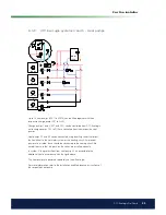
CTC EcoLogic system 1 – Heating circuit
The CTC EcoLogic can be connected to four different heating circuits, each
with separate room sensors. The diverting valve (Y21) is the main valve, and
the mixing valves (Y2, Y3 and Y4) are subsidiary valves.
The outdoor sensor (B15) must be itted to the outer wall of the house,
protected from direct sunlight. It is connected using a 2-conductor cable
(min. 0.5 mm²).
The room sensors (B11 to B14) must be itted in an open space in the
property where a representative temperature is expected. They are
connected using a 3-conductor cable (min. 0.5 mm²).
The primary low sensors (B1 to B4) must be placed on the primary low of
the respective heating circuit.
The sensor (B7) is placed on the return low from the heating circuit.
Heating circuit 4
Heating circuit 3
Heating circuit 2
Heating circuit 1
Содержание CTC EcoLogic Family series
Страница 2: ......
Страница 3: ...162 105 48 3 2016 04 08 Installation and Maintenance Manual CTC EcoLogic Pro Family...
Страница 67: ...67 CTC EcoLogic Pro Family For the property owner...
Страница 120: ...120 CTC EcoLogic Pro Family For the installer 11 Wiring diagram...
Страница 121: ...121 CTC EcoLogic Pro Family For the installer...
Страница 127: ......
Страница 128: ...Enertech AB P O Box 309 SE 341 26 Ljungby Sweden www ctc se www ctc heating com 162 105 48 3 2016 04 08...