


76
CTC EcoLogic Pro/Family
For the property owner
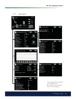
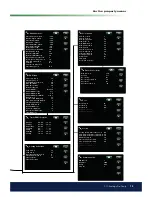
6. Parameter list
55
18
120
50
0
-2
-3
100
7
3
30
85
85
85
18
60
30
4
30
5
1
6
55
25
0
5
55
5
60
20
40
3
3
45
14
3
3
3
4
15
5
50
-500
-100
-500
-100
-500
-50
180
180
60
180
30
5
70
20
-22
-60
10
14
-60
30
7
-5
Radiator system
Factory
setting
User value
Max primary l ow ºC
Min primary l ow ºC
Off
Heating off, out ºC
Heating off, time
Inclination ºC
Adjustment ºC
Room temp reduced
Primary l ow reduced
Heating circ pump speed
Solar panels
dT max solar ºC
dT min solar ºC
Min speed pump %
Max boiler ºC
Max DHW tank ºC
Max buffer tank ºC
Max temp brine ºC
dT max ground ºC
dT min ground ºC
Solar test tank min
Test frequency min
Winter mode
Off
Time graph temp min
Time graph oper. min
Flow l/mln
Heating Buffer Tank
Tank max ºC
Tank min ºC
Diff tank vs primary ºC
Start/stop diff tank ºC
DHW tank
Factory
setting
User value
Stop temp HP ºC
Start/stop diff ºC
Extra DHW stop tempºC
Max time DHW
Max time heating
Delay heating calc
Add heat DHW
Demand
Add heat DHW relay
No
Add heat DHW 0-10V
Add heat DHW EcoMiniEL
3
Min temp ºC
Periodic extra DHW, days
Max temp diff end DHW ºC
Start/stop diff HP2 ºC
Stop DHW diff max
Run time DHW circ.
Time DHW circ
Diff start ext DHW buffer
Timer setpoint
Add heat
Start E1, degree minute
Diff E1, degree minute
Start 0-10V, ºminute
Diff 0-10V , ºminute
Start EcoMiniEl, ºminute
Diff step EcoMiniEl.
Delay add heat E1
Delay Add heat 0-10V
Diff 0-10V delay
Delay EcoMiniEl
Delay EcoMiniE step
Block add, outdoorºC
Boiler, open mixing v.ºC
Add heat max primary ºC
Off
Main fuse A
Start at l ue gas ºC
Off
Heat pump
Stop at outdoorºC
Start at degree minute
Max primary HP diffºC
Max primary HP Add diff ºC
Diff between comp.
Delay between comp.
Prio A/W ºC
Cont. brine pump on
No
Compressor stop at brineºC
Содержание CTC EcoLogic Family series
Страница 2: ......
Страница 3: ...162 105 48 3 2016 04 08 Installation and Maintenance Manual CTC EcoLogic Pro Family...
Страница 67: ...67 CTC EcoLogic Pro Family For the property owner...
Страница 120: ...120 CTC EcoLogic Pro Family For the installer 11 Wiring diagram...
Страница 121: ...121 CTC EcoLogic Pro Family For the installer...
Страница 127: ......
Страница 128: ...Enertech AB P O Box 309 SE 341 26 Ljungby Sweden www ctc se www ctc heating com 162 105 48 3 2016 04 08...