


10
CTC EcoLogic Pro/Family
General Information
G11
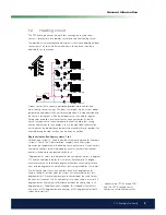
HP A1
1.2.1
Heat pump
The CTC EcoLogic can control up to ten heat pumps*, two of which can be
connected via diverting valves to deliver heat to either the heating circuit or
the hot water circuit.
Heat pump operation is a so-called loating condensation, where the
heat pump heats to the temperature required by the heating circuit. This
temperature varies depending on the outdoor temperature and which set
inclination and adjustment of the heat curve has been chosen. Installed room
sensors affect the temperature required in the heating circuit.
Savings from a heat pump are directly linked to the COP value. COP means
the output in proportion to the supplied power. Thus, COP = 3 means that
for 1 kW of supplied power from the compressor, 3 kW of heat output is
produced.
The lower the temperature the heat pump needs to produce, the higher the
COP value obtained from the heat pump, as this is a more advantageous
operation for the compressor. The heat pump therefore only heats to the
temperature required by the heating circuit. This is economical in terms of
the service life of the compressor and in maximising operating economy.
Buffer tank, EcoLogic systems 4 to 6
If a buffer tank is connected (see the schematic diagrams for EcoLogic
systems 4 to 6 in the “Pipe installation” chapter), the heating circuit can be
kept at a constant temperature.
The heat pump is controlled based on the temperature in the buffer tank.
The compressor starts at a certain predeined time after the sensor in the
tank measures a temperature that is lower than the setpoint for the tank and
stops when the tank measures a temperature difference that is set higher
than the setpoint for the tank. The indoor temperature in conjunction with the
outdoor temperature and chosen heat curve determine at which temperature
the primary low temperature will be aimed.
Buffer tank
*Applies to the CTC EcoLogic PRO
only. The CTC EcoLogic Family can
control up to two heat pumps.
Содержание CTC EcoLogic Family series
Страница 2: ......
Страница 3: ...162 105 48 3 2016 04 08 Installation and Maintenance Manual CTC EcoLogic Pro Family...
Страница 67: ...67 CTC EcoLogic Pro Family For the property owner...
Страница 120: ...120 CTC EcoLogic Pro Family For the installer 11 Wiring diagram...
Страница 121: ...121 CTC EcoLogic Pro Family For the installer...
Страница 127: ......
Страница 128: ...Enertech AB P O Box 309 SE 341 26 Ljungby Sweden www ctc se www ctc heating com 162 105 48 3 2016 04 08...