


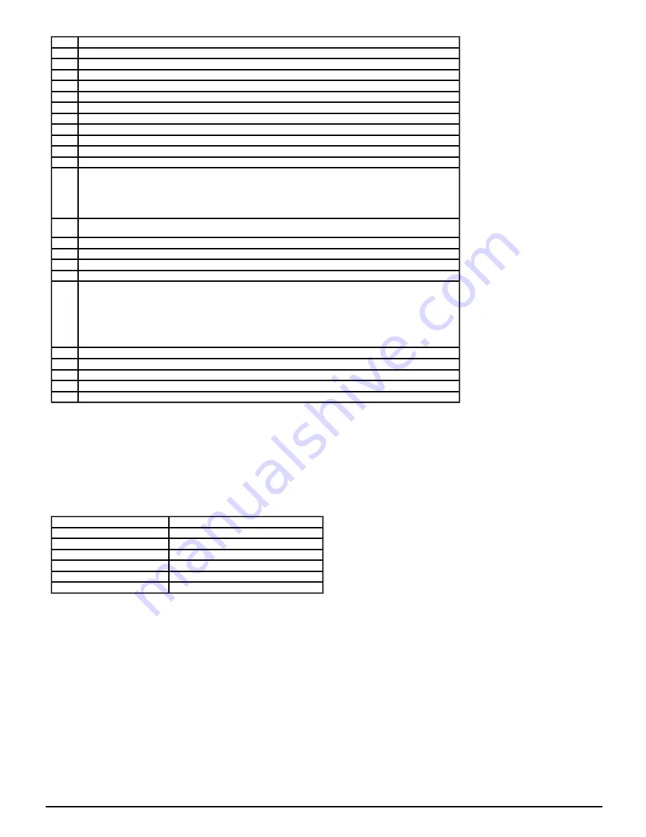
Trip
Reason
{
HF01
} CPU has detected an address error
{
HF02
} CPU DMAC has detected an address error
{
HF03
} CPU has detected an Illegal opcode
{
HF04
} CPU has detected an Illegal slot instruction
{
HF05
} An interrupt has occurred that does not have a defined function (Undefined exception)
{
HF06
} An interrupt has occurred which is reserved (Reserved exception)
{
HF07
} Watchdog failure
{
HF08
} CPU Interrupt crash
{
HF09
} Free store overflow
{
HF10
} Parameter routing system error
{
HF11
} Non-volatile memory comms error
{
HF12
}
Stack overflow. Sub-trip is shown to indicate which stack:
1 – background tasks
2 – timed tasks
3 – main system interrupts
{
HF13
} The control hardware is not compatible with the firmware. The sub-trip number gives the actual ID code of the
control board hardware.
{
HF14
} CPU register bank error
{
HF15
} CPU divide error
{
HF16
} RTOS error (the background task has returned)
{
HF17
} The clock supplied to the control board logic is out of specification
{
HF18
}
The internal flash memory has failed when writing option module parameter data.
Sub-trip is shown to indicate which failure:
1 - Programming error while writing menu in flash
2 - Erase flash block containing setup menus failed
3 - Erase flash block containing application menus failed
{
HF19
} Invalid main application firmware CRC. Reprogramming required.
{
HF20
} The ASIC is not compatible with the firmware. The sub-trip number displayed is the ASIC version.
{HF23} If this trip occurs please consult the drive supplier.
{HF24} If this trip occurs please consult the drive supplier.
{HF25} If this trip occurs please consult the drive supplier.
When the drive is subsequently powered up a
Stored HF
trip is initiated where the sub-trip number is the number of the HF trip that last occurred. This trip will occur
at every power-up until it is reset. The trip can only be reset by first entering 1299 into
Parameter mm.000
(mm.000). If the drive is powered up and a
Stored HF
trip
occurs,
Onboard User Program: Enable
(11.047) is reset to zero to prevent the on-board user program from running. This ensures that the user program can be
changed or erased in case it causes an HF trip at every power-up. Once the
Stored HF
is cleared, it is necessary to power cycle the drive or to re-download the user
program to allow the program to restart.
Similar trips that can be initiated by the control system or the power system
Trips shown in the table below can be generated either from the drive control system or from the power system. The sub-trip number which is in the form xxyzz is
used to identify the source of the trip. The digits xx are 00 for a trip generated by the control system or the number of a power module if generated by the power
system. If the drive is not a multi-power module drive then xx will always have a value of 1 the trip is related to the power system. The y digit is used to identify the
location of a trip which is generated by a rectifier module connected to a power module. Where the y digit is relevant it will have a value of 1 or more, otherwise it will
be 0. The zz digits give the reason for the trip and are defined in each trip description.
Over Volts
OHt dc bus
OI ac
Phase Loss
OI Brake
Power Comms
PSU
OI Snubber
OHt Inverter
Reserved 102
OHt Power
Temp Feedback
OHt Control
Power Data
Braking IGBT
The list below gives conditions that will disable the braking IGBT:
1.
Braking IGBT Upper Threshold
(06.074) = 0, or
Low Voltage Braking IGBT Threshold Select
(06.076) = 1 and
Low Voltage Braking IGBT Threshold
(06.075) = 0.
2. The drive is in the under-voltage state.
3. A priority 1, 2 or 3 trip is active (see
Trip 0
(10.020)).
4. One of the following trips is active or would be active if another trip is not already active:
OI Brake
,
PSU
,
Th Brake Res
or
OHt Inverter
.
5.
Percentage Of Drive Thermal Trip Level
(07.036) = 100%. This is an indication that some part of the drive is too hot and is used to indicate if an
internally fitted braking resistor is too hot.
6.
Brake R Too Hot
is active or the system has been set up to disable the braking IGBT based on the braking resistor temperature and the resistor is
too hot (i.e. bit 2 of
Action On Trip Detection
(10.037) is set).
Trips Summary
(numerical order)
Powerdrive F300 Parameter Reference Guide
Issue: 01.15.00
293
Содержание Powerdrive F300
Страница 1: ...Parameter Reference Guide Powerdrive F300 Open Loop Mode Issue 01 15 00 ...
Страница 20: ...Menu 1 Frequency References Mode Open Loop 20 Powerdrive F300 Parameter Reference Guide Issue 01 15 00 ...
Страница 21: ...Powerdrive F300 Parameter Reference Guide Issue 01 15 00 21 ...
Страница 36: ...Menu 2 Frequency Ramps Mode Open Loop 36 Powerdrive F300 Parameter Reference Guide Issue 01 15 00 ...
Страница 108: ...Menu 7 Single Line Descriptions Analog I O Mode Open Loop 108 Powerdrive F300 Parameter Reference Guide Issue 01 15 00 ...
Страница 112: ...112 Powerdrive F300 Parameter Reference Guide Issue 01 15 00 ...
Страница 144: ...144 Powerdrive F300 Parameter Reference Guide Issue 01 15 00 ...
Страница 168: ...Menu 10 Status and Trips Mode Open Loop 168 Powerdrive F300 Parameter Reference Guide Issue 01 15 00 ...
Страница 231: ...Powerdrive F300 Parameter Reference Guide Issue 01 15 00 231 ...
Страница 232: ...232 Powerdrive F300 Parameter Reference Guide Issue 01 15 00 ...


