Functional Description
ATCA-8310 Installation and Use (6806800M72D
)
86
The data rate for the serial interface links is set to 32.768 Mbps and the number of active serial
links is reduced to two.
4.4.4
SRIO Interface
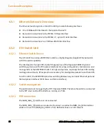
The TNETV3020 has two x1 SRIO interfaces which are cascaded to one chain with two
connections to the carrier board. The design is fault tolerant in a way that a single failure,
specifically the loss of one single DSP, does not cut the SRIO connection to functional DSPs.
The SRIO interfaces run with 1.25 Gb during boot operation and 2.5 Gb at normal operation.
4.4.5
RGMII Interface
Each TNETV3020 has a RGMII Ethernet interface which is connected to a dual PHY device
BCM5482S. The MDIO serial interface allows the DSP to configure the PHY devices and read
back PHY link information.
The BCM5482 offers an interface converter mode that supports RGMII-to-SGMII slave data
conversion. Each one of the PHY ports has a secondary SerDes that is used to perform
conversion.
4.4.6
DSP-FPGA
The DSP-FPGA is the main control unit on the DSP cluster. It controls all DSP functionality
including TSIP interface to the RTM and the power sequencing. The DSP-FPGA is connected to
service processor via SPI interface.
The configuration data are stored one SPI flash device. For update and recovery the SPP has
access to the configuration device.
Detailed functional informations are specified in detail within the FPGA Design Specification.
4.4.7
Module IPMC Interface
Each DSP module contains an EEPROM to storage FRU information. The interface is powered by
management power and connected to the IPMC via I2C.
Sensors and FRU information are specified in detail within the IPMC Design Specification.
Содержание ATCA-8310
Страница 12: ...ATCA 8310 Installation and Use 6806800M72D Contents 12 Contents Contents ...
Страница 26: ...ATCA 8310 Installation and Use 6806800M72D 26 List of Figures ...
Страница 34: ...ATCA 8310 Installation and Use 6806800M72D About this Manual 34 About this Manual ...
Страница 38: ...Introduction ATCA 8310 Installation and Use 6806800M72D 38 Figure 1 1 Declaration of Conformity ...
Страница 54: ...Hardware Preparation and Installation ATCA 8310 Installation and Use 6806800M72D 54 ...
Страница 70: ...Controls Indicators and Connectors ATCA 8310 Installation and Use 6806800M72D 70 ...
Страница 146: ...BIOS ATCA 8310 Installation and Use 6806800M72D 146 5 3 3 2 3 SATA Configuration Figure 5 32 SATA Configuration ...
Страница 162: ...BIOS ATCA 8310 Installation and Use 6806800M72D 162 ...
Страница 200: ...U Boot ATCA 8310 Installation and Use 6806800M72D 200 ...
Страница 244: ...Intelligent Peripheral Management Controller ATCA 8310 Installation and Use 6806800M72D 244 ...
Страница 438: ...CPLD and FPGA ATCA 8310 Installation and Use 6806800M72D 438 ...
Страница 442: ...Replacing the Battery ATCA 8310 Installation and Use 6806800M72D 442 ...
Страница 444: ...Related Documentation ATCA 8310 Installation and Use 6806800M72D 444 ...
Страница 454: ...ATCA 8310 Installation and Use 6806800M72D Sicherheitshinweise 454 ...
Страница 456: ...Index ATCA 8310 Installation and Use 6806800M72D 456 ...
Страница 457: ...Index ATCA 8310 Installation and Use 6806800M72D 457 ...
Страница 458: ...Index ATCA 8310 Installation and Use 6806800M72D 458 ...
Страница 459: ......


