CPLD and FPGA
ATCA-8310 Installation and Use (6806800M72D)
259
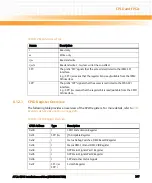
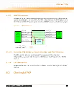
When the watchdog bites the IPMC is reset (drive H8S_RESET_ and H8s_ETRST_ low), the IPMC
latches are kept closed (CPLD_LATCH_LE driven low), and the IPMB buffers are disabled
(CPLD_IPMB0A_EN and CPLD_IPMB0B_EN are drive low) for about 100ms. The signal
H8S_WDOG_ACTIVE is deasserted and the Watchdog status signal H8S_WDOG_FLAG is set.
The signal H8S_WDOG_FLAG is cleared when the watchdog becomes active again.
The Watchdog can be disabled setting the SWITCH[3] (SW3.3) on.
8.1.5.2
IPMC IRQ
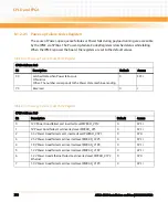
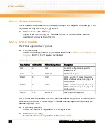
The CPLD can generate an IPMC interrupt to signal critical events:
z
GPP Thermal Trip. GPP_THERMTRIP_ asserted.
z
Dynamic Configuration Error. CONF_CRC_ERR asserted.
8.1.5.3
FPGA Configuration Logic
8.1.5.3.1 Status FPGA Configuration Load
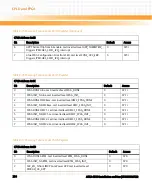
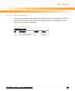
Each FPGA has two status signals FPGA_DONE and FPGA_INIT_. When both signals are high the
corresponding FPGA configuration was successful.
8.1.5.3.2 Trigger FPGA Configuration
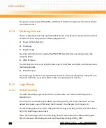
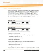
Each FPGA has a dedicated input, which can be used to reload the FPGA configuration. A short
low pulse triggers FPGA reload. Such a pulse can be generated writing a magic byte to the
corresponding CPLD register.
8.1.5.3.3 Force Golden FPGA Configuration
Each FPGA has an input, which can be used to corrupt the working image in corresponding
configuration SPI flash. A short low pulse triggers a logic (which have all Windsor FPGA in
common) to erase the first 4kB of the working image.
Such a pulse can be generated writing a magic byte to the corresponding CPLD register.
Содержание ATCA-8310
Страница 12: ...ATCA 8310 Installation and Use 6806800M72D Contents 12 Contents Contents ...
Страница 26: ...ATCA 8310 Installation and Use 6806800M72D 26 List of Figures ...
Страница 34: ...ATCA 8310 Installation and Use 6806800M72D About this Manual 34 About this Manual ...
Страница 38: ...Introduction ATCA 8310 Installation and Use 6806800M72D 38 Figure 1 1 Declaration of Conformity ...
Страница 54: ...Hardware Preparation and Installation ATCA 8310 Installation and Use 6806800M72D 54 ...
Страница 70: ...Controls Indicators and Connectors ATCA 8310 Installation and Use 6806800M72D 70 ...
Страница 146: ...BIOS ATCA 8310 Installation and Use 6806800M72D 146 5 3 3 2 3 SATA Configuration Figure 5 32 SATA Configuration ...
Страница 162: ...BIOS ATCA 8310 Installation and Use 6806800M72D 162 ...
Страница 200: ...U Boot ATCA 8310 Installation and Use 6806800M72D 200 ...
Страница 244: ...Intelligent Peripheral Management Controller ATCA 8310 Installation and Use 6806800M72D 244 ...
Страница 438: ...CPLD and FPGA ATCA 8310 Installation and Use 6806800M72D 438 ...
Страница 442: ...Replacing the Battery ATCA 8310 Installation and Use 6806800M72D 442 ...
Страница 444: ...Related Documentation ATCA 8310 Installation and Use 6806800M72D 444 ...
Страница 454: ...ATCA 8310 Installation and Use 6806800M72D Sicherheitshinweise 454 ...
Страница 456: ...Index ATCA 8310 Installation and Use 6806800M72D 456 ...
Страница 457: ...Index ATCA 8310 Installation and Use 6806800M72D 457 ...
Страница 458: ...Index ATCA 8310 Installation and Use 6806800M72D 458 ...
Страница 459: ......


