CPLD and FPGA
ATCA-8310 Installation and Use (6806800M72D
)
258
The power-up reset signal CPLD_PWR_GOOD resets all internal registers and state machines to
their default values.
8.1.4
Clocking Scheme
There are three clock domains inside the CPLD. The 1st clock domain is sourced by the internal
22 MHz clock and comprises the following logic blocks:
z
Power Up State Machine
z
Glue Logic
z
Register Logic
The 2nd clock domain is sourced by the IPMC SPI Master Interface and compromises the
following block:
z
IPMC SPI Slave
The 3rd clock domain is sourced by the Glue Logic FPGA SPI Master Interface and compromises
the following block:
z
FPGA SPI Slave
The entire logic blocks are running with the same clock at the same frequency. All signals from
other clock domains are synchronized to the corresponding clock domain.
8.1.5
Logic Blocks
8.1.5.1
IPMC Watchdog
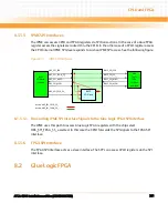
The IPMC Watchdog implemented in the CPLD emulates the external watchdog device
MAX6373KA.
The timeout is controllable by the IPMC signal H8S_WDOG_SET. When the level is low (the
default after power-up or IPMC reset) the timeout is 10s otherwise the timeout is 1s.
The Watchdog goes active after 3 H8S_WDI level changes and H8S_WDOG_ACTIVE is driven
high. The watchdog is now armed.
When the Watchdog is active the watchdog needs to be service before the watchdog bites
after the timeout. Watchdog is serviced with each level change of H8S_WDI.
Содержание ATCA-8310
Страница 12: ...ATCA 8310 Installation and Use 6806800M72D Contents 12 Contents Contents ...
Страница 26: ...ATCA 8310 Installation and Use 6806800M72D 26 List of Figures ...
Страница 34: ...ATCA 8310 Installation and Use 6806800M72D About this Manual 34 About this Manual ...
Страница 38: ...Introduction ATCA 8310 Installation and Use 6806800M72D 38 Figure 1 1 Declaration of Conformity ...
Страница 54: ...Hardware Preparation and Installation ATCA 8310 Installation and Use 6806800M72D 54 ...
Страница 70: ...Controls Indicators and Connectors ATCA 8310 Installation and Use 6806800M72D 70 ...
Страница 146: ...BIOS ATCA 8310 Installation and Use 6806800M72D 146 5 3 3 2 3 SATA Configuration Figure 5 32 SATA Configuration ...
Страница 162: ...BIOS ATCA 8310 Installation and Use 6806800M72D 162 ...
Страница 200: ...U Boot ATCA 8310 Installation and Use 6806800M72D 200 ...
Страница 244: ...Intelligent Peripheral Management Controller ATCA 8310 Installation and Use 6806800M72D 244 ...
Страница 438: ...CPLD and FPGA ATCA 8310 Installation and Use 6806800M72D 438 ...
Страница 442: ...Replacing the Battery ATCA 8310 Installation and Use 6806800M72D 442 ...
Страница 444: ...Related Documentation ATCA 8310 Installation and Use 6806800M72D 444 ...
Страница 454: ...ATCA 8310 Installation and Use 6806800M72D Sicherheitshinweise 454 ...
Страница 456: ...Index ATCA 8310 Installation and Use 6806800M72D 456 ...
Страница 457: ...Index ATCA 8310 Installation and Use 6806800M72D 457 ...
Страница 458: ...Index ATCA 8310 Installation and Use 6806800M72D 458 ...
Страница 459: ......


