


U-Boot
ATCA-8310 Installation and Use (6806800M72D)
173
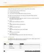
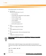
6.2.1.4.2 Environment Variables Passed to the GPP
The SPP passes information to the GPP in the first 512 bytes of the FPGA shared memory area.
The format of this shared memory area is:
z
Bytes 0/1 form the length code <len> (Byte 0 is the lsb, byte 1 the msb)
z
Bytes 2 .. <len>+1 contains the parameter information. Parameters are passed as zero-
terminated <name>=<value> ASCII strings. The last parameter string is terminated with
two zero bytes.
z
Bytes <len> + 2 (lsb) and <len>+3 (msb) contains the checksum over the parameter
information.
U-Boot initializes the parameter area with the following name/value pairs before releasing the
GPP from reset):
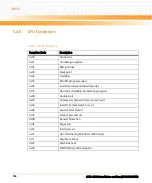
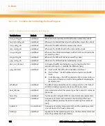
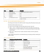
3
BIOS EnterSetup
The BIOS setup menu has been entered.
4
BIOS PrepareToBoot
XXX
15
BIOS Boot
XXX
29
BIOS end
XXX
>= 30
User defined OS run levels
Can be used by the Operating system to report further
progress messages.
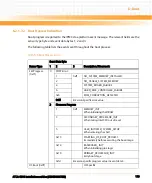
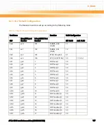
Table 6-4 GPP Run Levels (continued)
Value
Mnemonic
Description
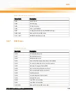
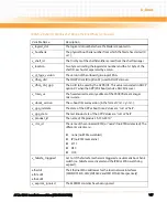
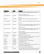
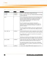
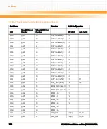
Table 6-5 U-Boot Name/Value Pairs
Name
Value (Corresponding U-Boot Variable)
Description
btime
$v_boottime
Boot time of blade
slot_p
$v_physical_slot
Physical slot of blade
slot_l
$v_logical_slot
Logical slot of blade
shelf
$v_shelf_id
Shelf identifier
sname
$v_shelf_name
The name of the shelf stored in the shelf FRU
information (product area).
spnum
$v_shelf_prid
The product ID of the shelf
Содержание ATCA-8310
Страница 12: ...ATCA 8310 Installation and Use 6806800M72D Contents 12 Contents Contents ...
Страница 26: ...ATCA 8310 Installation and Use 6806800M72D 26 List of Figures ...
Страница 34: ...ATCA 8310 Installation and Use 6806800M72D About this Manual 34 About this Manual ...
Страница 38: ...Introduction ATCA 8310 Installation and Use 6806800M72D 38 Figure 1 1 Declaration of Conformity ...
Страница 54: ...Hardware Preparation and Installation ATCA 8310 Installation and Use 6806800M72D 54 ...
Страница 70: ...Controls Indicators and Connectors ATCA 8310 Installation and Use 6806800M72D 70 ...
Страница 146: ...BIOS ATCA 8310 Installation and Use 6806800M72D 146 5 3 3 2 3 SATA Configuration Figure 5 32 SATA Configuration ...
Страница 162: ...BIOS ATCA 8310 Installation and Use 6806800M72D 162 ...
Страница 200: ...U Boot ATCA 8310 Installation and Use 6806800M72D 200 ...
Страница 244: ...Intelligent Peripheral Management Controller ATCA 8310 Installation and Use 6806800M72D 244 ...
Страница 438: ...CPLD and FPGA ATCA 8310 Installation and Use 6806800M72D 438 ...
Страница 442: ...Replacing the Battery ATCA 8310 Installation and Use 6806800M72D 442 ...
Страница 444: ...Related Documentation ATCA 8310 Installation and Use 6806800M72D 444 ...
Страница 454: ...ATCA 8310 Installation and Use 6806800M72D Sicherheitshinweise 454 ...
Страница 456: ...Index ATCA 8310 Installation and Use 6806800M72D 456 ...
Страница 457: ...Index ATCA 8310 Installation and Use 6806800M72D 457 ...
Страница 458: ...Index ATCA 8310 Installation and Use 6806800M72D 458 ...
Страница 459: ......


