


CPLD and FPGA
ATCA-8310 Installation and Use (6806800M72D
)
288
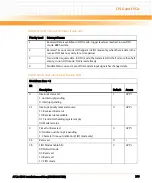
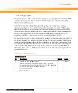
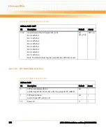
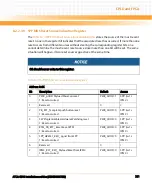
- Modem Status Register (MSR)
This 8-bit register provides the current state of the control lines from the modem or data set
(or a peripheral device emulating a modem) to the processor. In addition to this current state
information, four bits of the Modem Status register provide change information. Bits 03:00 are
set to a logic 1 when a control input from the Modem changes state. They are reset to a logic 0
when the processor reads the Modem Status register.
When bits 0, 1, 2, or 3 are set to logic 1, a Modem Status interrupt is generated if bit 3 of the
Interrupt Enable Register is set.
7
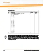
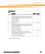
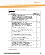
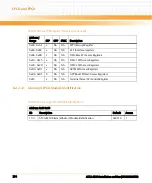
FIFO data error
In the FIFO mode, LSR7 is set when there is at least one parity,
framing, or break error in the FIFO. It is cleared when the
microprocessor reads the LSR and there are no subsequent errors
in the FIFO. If FIFO is not used, bit always reads 0:
1: FIFO data error encountered
0: No FIFO error encountered
0
GPP: r
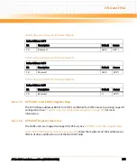
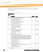
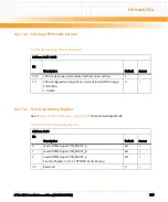
Table 8-60 Modem Status Register (MSR)
IO Address: Base + 6
Bit
Description
Default
Access
0
Change in clear-to-send (DCTS) indicator
DCTS indicates that the CTS# input has changed state since the
last time it was read by the CPU. When DCTS is set (autoflow
control is not enabled and the modem status interrupt is enabled),
a modem status interrupt is generated. When autoflow control is
enabled (DCTS is cleared), no interrupt is generated:
1: Change in state of CTS# input since last read
0: No change in state of CTS# input since last read
0
GPP: r/w
Table 8-59 Line Status Register (LSR) (continued)
IO Address: Base + 5
Bit Description
Default
Access
Содержание ATCA-8310
Страница 12: ...ATCA 8310 Installation and Use 6806800M72D Contents 12 Contents Contents ...
Страница 26: ...ATCA 8310 Installation and Use 6806800M72D 26 List of Figures ...
Страница 34: ...ATCA 8310 Installation and Use 6806800M72D About this Manual 34 About this Manual ...
Страница 38: ...Introduction ATCA 8310 Installation and Use 6806800M72D 38 Figure 1 1 Declaration of Conformity ...
Страница 54: ...Hardware Preparation and Installation ATCA 8310 Installation and Use 6806800M72D 54 ...
Страница 70: ...Controls Indicators and Connectors ATCA 8310 Installation and Use 6806800M72D 70 ...
Страница 146: ...BIOS ATCA 8310 Installation and Use 6806800M72D 146 5 3 3 2 3 SATA Configuration Figure 5 32 SATA Configuration ...
Страница 162: ...BIOS ATCA 8310 Installation and Use 6806800M72D 162 ...
Страница 200: ...U Boot ATCA 8310 Installation and Use 6806800M72D 200 ...
Страница 244: ...Intelligent Peripheral Management Controller ATCA 8310 Installation and Use 6806800M72D 244 ...
Страница 438: ...CPLD and FPGA ATCA 8310 Installation and Use 6806800M72D 438 ...
Страница 442: ...Replacing the Battery ATCA 8310 Installation and Use 6806800M72D 442 ...
Страница 444: ...Related Documentation ATCA 8310 Installation and Use 6806800M72D 444 ...
Страница 454: ...ATCA 8310 Installation and Use 6806800M72D Sicherheitshinweise 454 ...
Страница 456: ...Index ATCA 8310 Installation and Use 6806800M72D 456 ...
Страница 457: ...Index ATCA 8310 Installation and Use 6806800M72D 457 ...
Страница 458: ...Index ATCA 8310 Installation and Use 6806800M72D 458 ...
Страница 459: ......


