


Intelligent Peripheral Management Controller
ATCA-8310 Installation and Use (6806800M72D
)
206
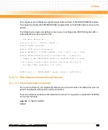
Each IPMI controller can be upgraded via KCS or IPMB interface. To ensure that the payload is
not interrupted during IPMI firmware upgrade, the IPMI controller is storing all operational
information (e-keying, hot-swap state, last events to be queued, graceful shutdown timeout,
latest pin settings…) in non-volatile storage.
7.5
Sensors
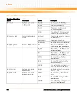
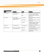
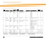
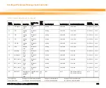
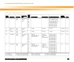
For a list of sensor identification numbers and information regarding the sensor type, name,
supported thresholds, assertion and deassertion information, and a brief description of the
sensor purpose, refer to
.
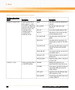
7.5.1
Firmware Progress, OS Boot, and Boot Error Sensor
The IPMC firmware provides a Firmware Progress, OS Boot, Boot Initiated and Boot Error
Sensor to enable SPP payload firmware and SPP payload OS to report boot progress and OS
Boot via IPMI event messages. In addition, a Firmware Progress sensor is implemented for the
Intel processor.
The firmware progress sensor is of type 0x0F (System Firmware Progress) and is used to pass
payload status information to the IPMC, which is then logged to the SEL (both local and
remote). While the payload is booting, the payload will log events to the Firmware Progress
Sensor to indicate where in its boot process it currently is.
The boot error sensor is of type 0x1E (Boot Error) and is used to pass boot failure information
to the IPMC, which is then logged to the SEL.
The OS Boot sensor is of type 0x1F (OS Boot) and is used to inform the IPMC when the
operating system has completed its boot up sequence.
7.5.2
Boot Bank Supervision Sensor
The boot bank supervision sensor is intended to always give the actual boot bank, from which
the payload has booted last. The boot bank information received from this sensor may differ
from the boot bank selection performed, in case of the boot bank selection has changed after
the payload has booted.
There are two Boot Bank Supervision Sensors, one for the Intel and another one for the SPP. The
Intel Boot Bank information is retrieved from the glue logic FPGA.
Содержание ATCA-8310
Страница 12: ...ATCA 8310 Installation and Use 6806800M72D Contents 12 Contents Contents ...
Страница 26: ...ATCA 8310 Installation and Use 6806800M72D 26 List of Figures ...
Страница 34: ...ATCA 8310 Installation and Use 6806800M72D About this Manual 34 About this Manual ...
Страница 38: ...Introduction ATCA 8310 Installation and Use 6806800M72D 38 Figure 1 1 Declaration of Conformity ...
Страница 54: ...Hardware Preparation and Installation ATCA 8310 Installation and Use 6806800M72D 54 ...
Страница 70: ...Controls Indicators and Connectors ATCA 8310 Installation and Use 6806800M72D 70 ...
Страница 146: ...BIOS ATCA 8310 Installation and Use 6806800M72D 146 5 3 3 2 3 SATA Configuration Figure 5 32 SATA Configuration ...
Страница 162: ...BIOS ATCA 8310 Installation and Use 6806800M72D 162 ...
Страница 200: ...U Boot ATCA 8310 Installation and Use 6806800M72D 200 ...
Страница 244: ...Intelligent Peripheral Management Controller ATCA 8310 Installation and Use 6806800M72D 244 ...
Страница 438: ...CPLD and FPGA ATCA 8310 Installation and Use 6806800M72D 438 ...
Страница 442: ...Replacing the Battery ATCA 8310 Installation and Use 6806800M72D 442 ...
Страница 444: ...Related Documentation ATCA 8310 Installation and Use 6806800M72D 444 ...
Страница 454: ...ATCA 8310 Installation and Use 6806800M72D Sicherheitshinweise 454 ...
Страница 456: ...Index ATCA 8310 Installation and Use 6806800M72D 456 ...
Страница 457: ...Index ATCA 8310 Installation and Use 6806800M72D 457 ...
Страница 458: ...Index ATCA 8310 Installation and Use 6806800M72D 458 ...
Страница 459: ......


