


Functional Description
ATCA-8310 Installation and Use (6806800M72D)
101
4.9.1.2
SPP-Reset
4.9.1.2.1 Cold Reset
A cold reset is issued by either the PORESET# or the HRESET# signal.
4.9.1.2.2 Warm Reset
Warm Reset is Is done by the software.
4.9.1.3
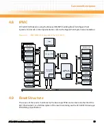
Reset Sources
4.9.1.3.1 Power-up Reset
The power-up reset (BRD_PWROK) is activated during power-up or power-down and is
deactivated when all onboard supply voltages are within their threshold voltages. Power-up
reset generates a Cold reset on ATCA-8310 resetting all attached onboard devices. The power-
up reset signal BRD_PWROK is connected to the Glue Logic FPGA which propagates it to the
PWROK input of the P4080 (respecting the PWROK input min. assertion of 99msec). The DDR3
DIMMs are reset directly from the processors individually per memory channel and CPU during
power-up only, according DDR specification.
4.9.1.3.2 Software Controlled Reset
Software is able to generate a Cold and a Warm reset. Depending on the configuration.
4.9.1.3.3 Face Plate Reset
A pinhole reset switch is available on the face plate. Hitting the face plate reset generates a
reset on ATCA-8310 resetting all attached onboard devices. The reset switch must be enabled
through IPMC.
The reset switch will be recessed and can be covered by overlay foil.
4.9.1.3.4 RTM Reset
An RTM reset causes a reset on ATCA-8310 resetting all attached onboard devices.
Содержание ATCA-8310
Страница 12: ...ATCA 8310 Installation and Use 6806800M72D Contents 12 Contents Contents ...
Страница 26: ...ATCA 8310 Installation and Use 6806800M72D 26 List of Figures ...
Страница 34: ...ATCA 8310 Installation and Use 6806800M72D About this Manual 34 About this Manual ...
Страница 38: ...Introduction ATCA 8310 Installation and Use 6806800M72D 38 Figure 1 1 Declaration of Conformity ...
Страница 54: ...Hardware Preparation and Installation ATCA 8310 Installation and Use 6806800M72D 54 ...
Страница 70: ...Controls Indicators and Connectors ATCA 8310 Installation and Use 6806800M72D 70 ...
Страница 146: ...BIOS ATCA 8310 Installation and Use 6806800M72D 146 5 3 3 2 3 SATA Configuration Figure 5 32 SATA Configuration ...
Страница 162: ...BIOS ATCA 8310 Installation and Use 6806800M72D 162 ...
Страница 200: ...U Boot ATCA 8310 Installation and Use 6806800M72D 200 ...
Страница 244: ...Intelligent Peripheral Management Controller ATCA 8310 Installation and Use 6806800M72D 244 ...
Страница 438: ...CPLD and FPGA ATCA 8310 Installation and Use 6806800M72D 438 ...
Страница 442: ...Replacing the Battery ATCA 8310 Installation and Use 6806800M72D 442 ...
Страница 444: ...Related Documentation ATCA 8310 Installation and Use 6806800M72D 444 ...
Страница 454: ...ATCA 8310 Installation and Use 6806800M72D Sicherheitshinweise 454 ...
Страница 456: ...Index ATCA 8310 Installation and Use 6806800M72D 456 ...
Страница 457: ...Index ATCA 8310 Installation and Use 6806800M72D 457 ...
Страница 458: ...Index ATCA 8310 Installation and Use 6806800M72D 458 ...
Страница 459: ......


