


CPLD and FPGA
ATCA-8310 Installation and Use (6806800M72D
)
278
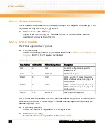
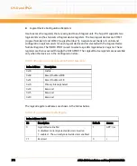
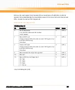
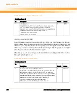
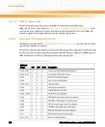
This register enables four types of interrupts which independently activate the int signal and
set a value in the Interrupt Identification Register. Each of the four interrupt types can be
disabled by resetting the appropriate bit of the IER register. Similarly, by setting the
appropriate bits, selected interrupts can be enabled.
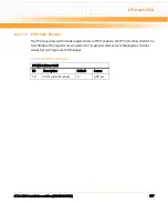
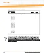
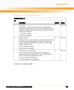
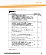
- Interrupt Identification Register (IIIR)
In order to minimize software overhead during data character transfers, the UART prioritizes
interrupts into four levels (listed in
Table 8-53UART Interrupt Priorities2
) and records these in
the Interrupt Identification Register. The Interrupt Identification Register (IIR) stores
information indicating that a prioritized interrupt is pending and the source of that interrupt.
Table 8-52 Interrupt Enable Register (IER), if DLAB=0
IO Address: Base + 1
Bit
Description
Default
Access
0
Receive data interrupt enable/disable:
1: receive data interrupt enabled
0: receive data interrupt disabled
0
GPP: r/w
1
Transmitter holding register empty (THRE) interrupt
enable/disable
1: THRE interrupt enabled
0: THRE interrupt disabled
0
GPP: r/w
2
Receiver line status interrupt enable/disable
1: receiver line status interrupt enabled
0: receiver line status interrupt disabled
0
GPP: r/w
3
Modem status interrupt enable/disable:
1: modem status interrupt enabled
0: modem status interrupt disabled
0
GPP: r/w
7:4
Reserved
0
r
Table 8-53 UART Interrupt Priorities2
Priority Level
Interrupt Source
1 (highest)
Receiver Line Status. One or more error bits were set.
Содержание ATCA-8310
Страница 12: ...ATCA 8310 Installation and Use 6806800M72D Contents 12 Contents Contents ...
Страница 26: ...ATCA 8310 Installation and Use 6806800M72D 26 List of Figures ...
Страница 34: ...ATCA 8310 Installation and Use 6806800M72D About this Manual 34 About this Manual ...
Страница 38: ...Introduction ATCA 8310 Installation and Use 6806800M72D 38 Figure 1 1 Declaration of Conformity ...
Страница 54: ...Hardware Preparation and Installation ATCA 8310 Installation and Use 6806800M72D 54 ...
Страница 70: ...Controls Indicators and Connectors ATCA 8310 Installation and Use 6806800M72D 70 ...
Страница 146: ...BIOS ATCA 8310 Installation and Use 6806800M72D 146 5 3 3 2 3 SATA Configuration Figure 5 32 SATA Configuration ...
Страница 162: ...BIOS ATCA 8310 Installation and Use 6806800M72D 162 ...
Страница 200: ...U Boot ATCA 8310 Installation and Use 6806800M72D 200 ...
Страница 244: ...Intelligent Peripheral Management Controller ATCA 8310 Installation and Use 6806800M72D 244 ...
Страница 438: ...CPLD and FPGA ATCA 8310 Installation and Use 6806800M72D 438 ...
Страница 442: ...Replacing the Battery ATCA 8310 Installation and Use 6806800M72D 442 ...
Страница 444: ...Related Documentation ATCA 8310 Installation and Use 6806800M72D 444 ...
Страница 454: ...ATCA 8310 Installation and Use 6806800M72D Sicherheitshinweise 454 ...
Страница 456: ...Index ATCA 8310 Installation and Use 6806800M72D 456 ...
Страница 457: ...Index ATCA 8310 Installation and Use 6806800M72D 457 ...
Страница 458: ...Index ATCA 8310 Installation and Use 6806800M72D 458 ...
Страница 459: ......


