


Diagnostics Optimization CT MODBUS RTU Technical Data
E300 Design Guide
161
Issue Number: 1
Table 7-12 Calculated and user deceleration distances
Table 7-13 Direct to floor parameters
Table 7-14 Direct to floor sensor mode
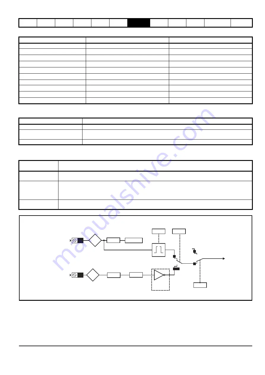
Figure 7-6 Stop signal for Direct to floor
Direct to floor operation utilizes a feature of digital input 4, which bypasses the normal input logic resulting in a fast response to a change in the input
signal, such that when the sensor is activated the signal is sampled in <1 µs. When digital input 4 is used for the Direct to floor slowing signal, it is
recommended that the input is not used for any other purpose and
Digital Input 4 Destination
(
F21
) should be set to a value of 'A00'. It is possible to
specify whether the positive or negative edge of the floor sensor correction signal is detected using
Direct To Floor Edge Detection
(
H10
).
Speed
Calculated Deceleration Distance
User Deceleration Distance
V1 Speed Reference
(
G01
)
V1 Calculated Deceleration Distance
(
J10
)
V1 Deceleration Distance Setpoint
(
G19
)
V2 Speed Reference
(
G02
)
V2
Calculated Deceleration Distance
(
J11
)
V2 Deceleration Distance Setpoint
(
G20
)
V3 Speed Reference
(
G03
)
V3
Calculated Deceleration Distance
(
J12)
V3 Deceleration Distance Setpoint
(
G21
)
V4 Speed Reference
(
G04
)
V4
Calculated Deceleration Distance
(
J13)
V4 Deceleration Distance Setpoint
(
G22
)
V5 Speed Reference
(
G05
)
V5
Calculated Deceleration Distance
(
J14
)
V5 Deceleration Distance Setpoint
(
G23
)
V6 Speed Reference
(
G06
)
V6
Calculated Deceleration Distance
(
J15)
V6 Deceleration Distance Setpoint
(
G24
)
V7 Speed Reference
(
G07
)
V7 Calculated Deceleration Distance
(
J16
)
V7 Deceleration Distance Setpoint
(
G25
)
V8 Speed Reference
(
G08
)
V8
Calculated Deceleration Distance
(
J17
)
V8 Deceleration Distance Setpoint
(
G26
)
V9 Speed Reference
(
G09
)
V9
Calculated Deceleration Distance
(
J18
)
V9 Deceleration Distance Setpoint
(
G27
)
V10 Speed Reference
(
G10
)
V10
Calculated Deceleration Distance
(
J19
)
V10 Deceleration Distance Setpoint
(
G28
)
Parameter
Details
Elevator Control Mode
(
H19
)
Selects creep to floor or direct to floor positioning.
Direct To Floor Sensor Mode
(
H09
)
Selects whether a stop signal digital input 4 or the removal of speed signals is used to trigger a direct to
floor stop.
Direct To Floor Edge Detection
(
H10
)
Selects whether a positive or negative edge of the stop signal is detected.
Direct To Floor
Sensor Mode
(H09)
Details
Spd IP (0)
Stopping is activated by a removal of the speed signals. The deceleration distance is calculated from the profile
parameters and is displayed in
V1 Calculated Deceleration Distance
(
J10
)
>
V10 Calculated Deceleration Distance
(
J19
).
Stop IP (1)
Stopping is activated by a stop signal via digital input 4 (control terminal 27). The deceleration distance is calculated from
the profile parameters and is displayed in
V1 Calculated Deceleration Distance
(J10)
>
V10 Calculated Deceleration
Distance
(
J19
). Edge detection is selected by
Direct To Floor Edge Detection
(
H10
) selects rising (0) or falling (1) edge
detection.
Spd IP+User Dist (2)
Stopping is activated by a removal of the speed signals. The user can specify the deceleration distance used directly using
V1 Deceleration Distance Setpoint
(
G19
) to
V10 Deceleration Distance Setpoint
(
G28
).
Digital
Input 4
Digital
Input Y
Loss Of
Speed
Signals
Digital
Input Y
Invert
Digital
Input Y
Destination
Digital
Input Y
State
Digital
Input 4
Invert
Digital
Input 4
Destination
Direct To Floor
Edge Detection
Elevator
Control
Mode
Stop signal
Digital
Input 4
State
T27
F15
H10
H09
H19
F21=A00
F06
Txx
1
0 or 2
0
1
Stop signal
Direct To Floor
Sensor
Mode
Creep
To Floor
Direct
To
Floor
Any Speed signal
Содержание 03200106
Страница 490: ...0479 0024 01 ...


