


70
English
The three components slide into each other with relatively minimal clearance. The components
will wear in due course and, therefore, play will increase. Avoid undue free play because this will
cause unwanted vibrations and, moreover, this will weaken the components and, thus, the risk of
a breakage will be greater. Regularly check the condition of the elastic coupling and, if excessive
wear has occurred, replace it.
Spare parts are available from an authorized ELIET dealer by using the above order numbers.
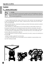
• Switch off the engine and remove the key from the ignition to carry out this maintenance task.
• Open the left shielding panel (see § AP.A-P1).
• Remove the black air box. Undo the 4 M6 bolts (M6) securing this box. (A/F 10) Disconnect, if
appropriate, the hydraulic lines and the air fi lter located on top of the air box.
• The hydraulic pump is fi xed on a bed plate that, in turn, is secured to the engine using 4 rubber
vibration absorbers.
• Remove the bed plate by undoing the 4 nuts (M6 – A/F 10).
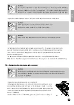
• Disconnect the aluminium coupling assembly from the pump shaft. Fold the sealing lips and
loosen the nut (A/F 11). The shaft is conical which makes coupling assembly removal very easy.
• When fi tting the new coupling assembly, keep the small key in mind to ensure it is fi tted correctly.
• A base accommodating two wings is secured to the coupling assembly. This is important to the
speed sensor that is also fi xed to the pump bed plate.
• For correct speed detection, it is essential that the distance when the nearest wing passes past the
sensor face is 6 mm. Measure this distance accurately and, if required, adjust the sensor slightly.
• Loosen the large check nut to adjust the sensor (A/F size 36). The full length of the sensor body
is threaded so that you can it turn in or out the sensor according to the required adjustment.
• The coupling assembly of the petrol engine is screw fi xed to the crankshaft. The round base
with oblong slots behind the coupling assembly should be used to secure it in position. Loosen
the two bolts of this locking base (M6 – hex A/F 6) fi rst and then loosen the coupling assembly.
When fi tting the new coupling assembly, fi rst tighten it completely down before securing the
bolts in the locking base.
• Insert the fl ector in between the two coupling assemblies and refi t the engine bed plate in its
original position. Avoid any strain on the coupling when refi tting. This will prevent premature wear
to the coupling parts.
• When replacing the air box, make sure to fi x the box as close as possible to the engine and the
hydraulic lines to minimise the risk of air gaps. This
will ensure that fresh cooling air cannot mix too much
with hot air that may be suctioned along these gaps.
• On refi tting the hydraulic lines and/or the air fi lter
to the air box, ensure that everything is fi xed with-
out creating stresses and strains before doing the
fi nal tightening.
• Do not omit to carefully refi t and close the shield-
ing panel upon completion of servicing.