


64
English
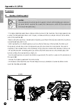
• The belt should be tensioned by sliding the engine forward
using a tensioning system. Loosen the 4 securing bolts (M10) (1)
of the motor bed plate. (A/F 17). The nuts do not have to be fully
unscrewed, 1 turn is suffi cient to remove the tension.
(1)
• Disassemble the two support rollers so that the confi guration
of the belt cannot be infl uenced. (M10 – A/F 17). Use this oppor-
tunity to lubricate this support rollers.
(2)
• Pull the motor bed plate forward by using an eye bolt to re-
store belt tension. (See fi gure). Tighten the nut (M10) clockwise.
(A/F 17)
(3)
• You can obtain the correct belt tension if you apply a point
charge of 8 kg halfway through the distance between the cen-
tres of the pulleys and you can measure a defl ection of 10 mm
on the belt.
(4)
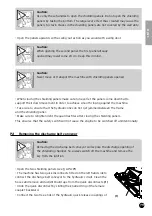
• Once the correct tension has been achieved, align both the
pulleys. To this effect, a bolt (M10) is provided. By turning this
clockwise, you can pull the motor bed plate towards yourself.
(A/F 17). Realign the drive pulley in this way with the pulley on
the blade shaft.
(5)
• To see whether the belt pulleys are correctly aligned, use a
straight strip of wood with a sharp edge (l= 1,200 mm), and hold
the sharp edge against both belt pulleys. When the alignment is
correct, the strip of wood will touch the belt pulleys at 4 loca-
tions.
(6)
• Once the pulleys have been correctly aligned, retighten the 4
bolts of the motor bed plate (M10 – A/F 17) (torque loading 49 Nm).
• Refi t the support rollers and position these so that both have
approximately 0.5 to 1 mm clearance with the belt. (M10 – A/F 17)
• Carefully close the safety guard upon completion of these
maintenance tasks (see § AP.A-P1).
(1)
(2)
(3)
(4)
(5)
(6)
10 mm
8 kg
1/2 L