xiv
6205s BATHYMETRIC AND SIDE SCAN SONAR
0020300_REV_E
LIST OF FIGURES
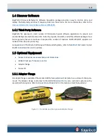
Figure 1-1: The 6205s and the Optional Adaptor Flange ........................................................................... 1-3
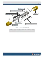
Figure 2-1: 6205s Sonar Head Components .............................................................................................. 2-5
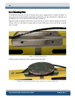
Figure 2-2: The Mounting Plate ................................................................................................................. 2-6
Figure 2-3: The Optional Adaptor Flange Installed onto the Mounting Plate ........................................... 2-6
Figure 2-4: 6205s Electronics Housing and Arrays Installed ...................................................................... 2-8
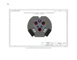
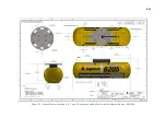
Figure 2-5: Acoustic Center Location in X, Y, and Z and Bolt Pattern of Standard 6205s – 0019604 ...... 2-10
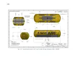
Figure 2-6: Acoustic Center Location in X, Y, and Z Dimensions and Bolt Pattern with Adaptor Flange –
0021206 ................................................................................................................................................... 2-11
Figure 3-1: Rack Mount Topside .............................................................................................................. 3-16
Figure 3-2: 6205s-P Portable Topside ...................................................................................................... 3-17
Figure 3-3: 6205s-P Portable Topside Interface Box, Side View .............................................................. 3-17
Figure 3-4: 6205s Exploded View ............................................................................................................. 3-19
Figure 3-5: 6205s Exploded View with Adaptor Flange ........................................................................... 3-20
Figure 3-6: 6205s Transducer................................................................................................................... 3-21
Figure 3-7: 6205s Array Color Codes Diagram ......................................................................................... 3-22
Figure 3-8: 6205s Wiring Diagram – 0019627 ......................................................................................... 3-23
Figure 4-1: 6205s Rack Mount Topside Interface Connections ............................................................... 4-26
Figure 4-2: 6205s-R Rack Mount Topside Interface Connections ............................................................ 4-28
Figure 4-3: Figure 4 3: 6205S System Is Optimized To Work With A Falling Edge 1PPS Signal................ 4-30
Figure 4-4: Sonar Data Flowchart ............................................................................................................ 4-31
Figure 4-5: Chevron Pattern Noise in a Cropped Portion of Discover Bathymetric ................................ 4-33
Figure 5-1: 6205s Deployment, Option 1 – Over-the-Bow ...................................................................... 5-35
Figure 5-2: 6205s Deployment, Option 2 – Over-the-Side ...................................................................... 5-36
Figure 5-3: 6205s Deployment, Option 3 – to a USV (Sea Robotics in this example) .............................. 5-37
Figure 5-4: Unit on Stable Platform ......................................................................................................... 5-38
Figure 5-5: Removing the Cap Screws...................................................................................................... 5-39
Figure 5-6: Top Housing and Deck Cable Removed ................................................................................. 5-39
Figure 5-7: Remove the Center Bracket ................................................................................................... 5-40
Figure 5-8: Remove the Portion of the Shell ‘EdgeTech’ and the Logo ................................................... 5-40
Figure 5-9: The Disconnected Bathymetry and Side Scan Sonar Cables .................................................. 5-41
Figure 5-10: Remove the [6] Cap Screws ................................................................................................. 5-41
Figure 5-11: All Cap Screws Removed ...................................................................................................... 5-42
Содержание 6205S
Страница 27: ...2 10 Figure 2 5 Acoustic Center Location in X Y and Z and Bolt Pattern of Standard 6205s 0019604...
Страница 28: ...2 11 Figure 2 6 Acoustic Center Location in X Y and Z Dimensions and Bolt Pattern with Adaptor Flange 0021206...
Страница 37: ...3 20 Figure 3 5 6205s Exploded View with Adaptor Flange...
Страница 38: ...3 21 Figure 3 6 6205s Transducer...
Страница 40: ...3 23 Figure 3 8 6205s Wiring Diagram 0019627...
Страница 86: ...8 69 Figure 8 22 Checking all COM Ports...
Страница 92: ...8 75 Figure 8 28 UDP broadcast settings example Figure 8 29 Eth1 data output...
Страница 94: ...8 77 Figure 8 31 1PPS settings example Falling Edge and 1msec duration...


