4-25
NOTE:
The prefix “$xx” represents proprietary NMEA message prefix for
a specific manufacturer. $GPGGA, $GPZDA, etc. are example NMEA
output sentences for a Hemisphere GPS.
We recommend you also supply the system with a source of Speed Over
Ground in NMEA format (i.e., VTG, minimum of 1Hz) so that the system
can correctly compute Along-Track Distance between each ping and
display it in Discover Bathymetric Software.
Messages can be sent over an ethernet connection via UDP functionality.
4.2
System Connections and Data Flow
The following sub-sections describe the connections and data flow for the 6205s System.
4.2.1
Ethernet LAN Connections
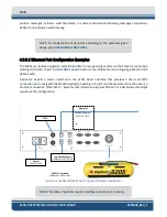
The Ethernet LAN connection from the sonar head to the 6205s topside interface is made using a physical
wired connection via a 1m (40inch) pigtail extension and the standard 20m (65 ft) Deck Cable. The 6205s
sonar interface then connects to a topside computer via a standard RJ-45 ethernet plug. The correct IP
addresses for the sonar head and topside computer are listed below. The 6205s sonar interface then
connects to a Topside Computer via a standard RJ-45 Ethernet plug. The correct IP addresses for the sonar
head and Topside Computer are listed below.
•
Sonar Head IP Address = 192.9.0.101
•
Topside Computer IP Address = 192.9.0.99
NOTE:
Factory defaults for the 6205s Sonar head IP address is
192.9.0.101 and should not be changed for any reason. The supplied
laptop with the 6205s-P portable topside interface will also be
preconfigured to 192.9.0.99 on delivery from the factory. If the customer
supplies their own topside computer, the IP address needs to be set to
the address above.
The 6205s can receive data from supporting sensors via the ethernet connection utilizing UDP. Refer to
section of the manual for more information on configuring 6205s for UDP data
transfer.
Содержание 6205S
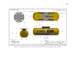
Страница 27: ...2 10 Figure 2 5 Acoustic Center Location in X Y and Z and Bolt Pattern of Standard 6205s 0019604...
Страница 28: ...2 11 Figure 2 6 Acoustic Center Location in X Y and Z Dimensions and Bolt Pattern with Adaptor Flange 0021206...
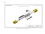
Страница 37: ...3 20 Figure 3 5 6205s Exploded View with Adaptor Flange...
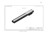
Страница 38: ...3 21 Figure 3 6 6205s Transducer...
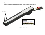
Страница 40: ...3 23 Figure 3 8 6205s Wiring Diagram 0019627...
Страница 86: ...8 69 Figure 8 22 Checking all COM Ports...
Страница 92: ...8 75 Figure 8 28 UDP broadcast settings example Figure 8 29 Eth1 data output...
Страница 94: ...8 77 Figure 8 31 1PPS settings example Falling Edge and 1msec duration...

