8-67
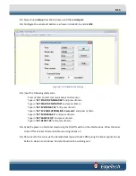
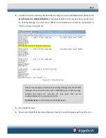
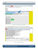
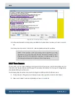
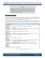
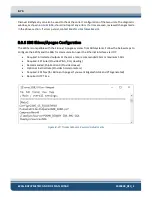
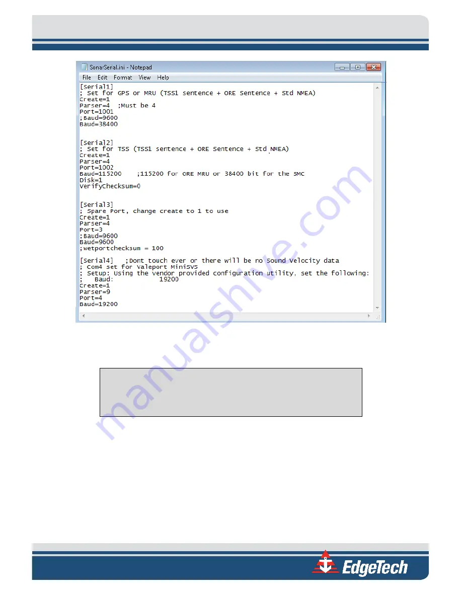
Figure 8-21: All Sensors Set
3.
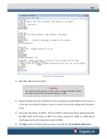
Select
File
>
Save
and close the file.
CAUTION!
Do not touch anything else, or the system’s configuration files could be
seriously compromised, and functionality may suffer.
4.
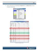
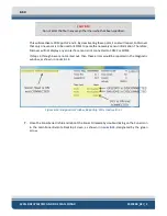
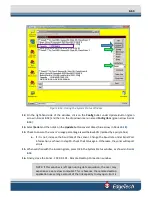
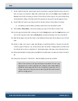
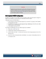
Close the SonarSerial.ini file and reboot the Sonar Firmware by double-clicking on the Sonar icon
in the main Sonar Remote Desktop Screen, as shown in
designated by the green
arrow.
5.
Now, plug in the devices into COM 1, COM 2, and COM 3. The Gyro should be connected to COM1,
the MRU COM2, and the GPS to COM3. The devices connected to COM1 or COM2 may be
interchanged, but the GPS must be connected to COM3.
6.
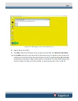
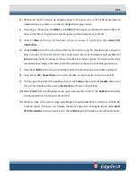
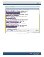
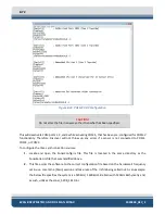
Click
Misc.
at the top of Sonar screen, as shown in
, then
Serial Port Information.
Содержание 6205S
Страница 27: ...2 10 Figure 2 5 Acoustic Center Location in X Y and Z and Bolt Pattern of Standard 6205s 0019604...
Страница 28: ...2 11 Figure 2 6 Acoustic Center Location in X Y and Z Dimensions and Bolt Pattern with Adaptor Flange 0021206...
Страница 37: ...3 20 Figure 3 5 6205s Exploded View with Adaptor Flange...
Страница 38: ...3 21 Figure 3 6 6205s Transducer...
Страница 40: ...3 23 Figure 3 8 6205s Wiring Diagram 0019627...
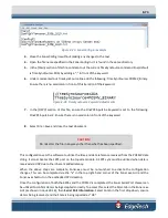
Страница 86: ...8 69 Figure 8 22 Checking all COM Ports...
Страница 92: ...8 75 Figure 8 28 UDP broadcast settings example Figure 8 29 Eth1 data output...
Страница 94: ...8 77 Figure 8 31 1PPS settings example Falling Edge and 1msec duration...

