ECOWATER
S Y S T E
M S
Planning Installation
7
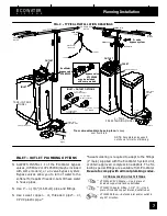
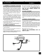
FIG. 3 -- TYPICAL INSTALLATION DRAWINGS
INLET -- OUTLET OPTIONS
1”copper tube
(2 supplied)
1’x 1”strgt.
sweat connector
1’x 3/4”strgt.
sweat connector
1”sweat x 1”or 3/4”
pipe thread
floor drain
floor drain
NOTE: Faceplate and support
not shown for clarity of drawing.
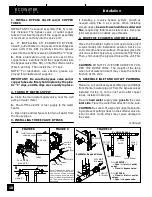
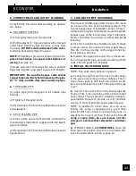
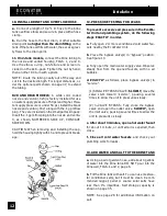
Tie or wire valve drain hose in place,
to keep
over floor drain.
valve drain hose
valve drain hose
brine tank
overflow
hose
brine tank
overflow hose
2 -- TANK,
FREESTANDING MODEL
TANK--IN--TANK
MODEL
1--1/2”
airgap
120V, 60Hz
outlet
transformer
(supplied)
to timer
to timer
1--1/2”
airgap
INLET
INLET
OUTLET
OUTLET
EcoWater
bypass valve
#7083122
3-- valve
bypass system
inlet
valve
outlet
valve
bypass
valve
HARD
WATER
HARD
WATER
CONDITIONED
WATER
bypass valve
#7195408
may be included
with some models
INLET -- OUTLET PLUMBING OPTIONS
S
ALWAYS INSTALL 1 of the EcoWater bypass
valves, #7083122 or #7195408 (may be included
with some models), or a 3 valve bypass system.
Bypass valves allow you to turn of water to the
softener for repairs if needed, but still have water
in house pipes.
S
Use 1”... or, 3/4”(minimum) pipe and fittings.
S
Use sweat copper... or, threaded pipe*... or,
CPVC plastic pipe.*
*Sweat soldering is required to adapt to the fittings
(1”male) supplied with the EcoWater System Unit,
or obtain approved compression adaptors. The fol-
lowing special fittings are available from EcoWater.
Be sure to comply with all local plumbing codes.
OPTIONAL INLET/OUTLET FITTINGS
#7104546 CPVC Nipple --- Use in place of
included copper inlet and outlet tubes.
#7129211 Adaptor Fitting, 1–1/2”(2) --- Use in
place of included copper inlet and outlet tubes.
#7120259 Elbow --- Extends inlet and/or outlet in
any 90° direction.


